Methods for the Discovery of Novel Compounds Modulating a Gamma-Aminobutyric Acid Receptor Type A Neurotransmission
Summary
Here, we present protocols to discover compounds active at GABAA receptors, from the binding to the physiology and pharmacology.
Abstract
This manuscript presents a step-by-step protocol for screening compounds at gamma-aminobutyric acid type A (GABAA) receptors and its use towards the identification of novel molecules active in preclinical assays from an in vitro recombinant receptor to their pharmacological effects at native receptors in rodent brain slices. For compounds binding at the benzodiazepine site of the receptor, the first step is to set up a primary screen that consists of developing radioligand binding assays on cell membranes expressing the major GABAA subtypes. Then, taking advantage of the heterologous expression of rodent and human GABAA receptors in Xenopus oocytes or HEK 293 cells, it is possible to explore, in electrophysiological assays, the physiological properties of the different receptor subtypes and the pharmacological properties of the identified compounds. The Xenopus oocyte system will be presented here, starting with the isolation of the oocytes and their microinjection with different mRNAs, up to the pharmacological characterization using two-electrode voltage clamps. Finally, recordings conducted in rodent brain slices will be described that are used as a secondary physiological test to assess the activity of molecules at their native receptors in a well-defined neuronal circuit. Extracellular recordings using population responses of multiple neurons are demonstrated together with the drug application.
Introduction
Here, we present protocols for the discovery of compounds active at GABAA receptors, from the binding to the physiology and pharmacology. In the search for novel molecules specific for GABAA receptors, it is crucial to define, as precisely as possible, the subtype of interest and the assessment of the specificity of the newly identified compounds (e.g., for a review, see Rudolph and Knoflach1or Sieghart2). A typical path in drug discovery and the steps that need to be achieved are illustrated in Figure 1.
Binding assays have been and are still largely used as the first step in drug discovery. In the case of GABAA receptors, they are optimized to identify compounds that bind to the benzodiazepine binding site of the receptor where therapeutically useful and safe drugs bind. Other techniques, using fluorometric imaging plate reader (FLIPR) membrane potential red dye-based assays3, detect compounds like barbiturates that bind to additional sites that are less desirable due to their unwanted side-effect profile. In addition, the utilized dyes can directly activate GABAA receptors, thus questioning the utility of these assays for drug discovery4. Binding assays can only provide the evidence that a given compound can bind to a specific receptor class. In vitro assays with cell membranes are used to identify selective human GABAA α5β3γ2 receptor ligands. Transiently transfected HEK293 cells expressing the human GABAA α5β3γ2, α1β3γ2, α2β3γ2, and α3β3γ2 receptors are used to prepare membranes for these assays. The effect of the ligands is detected by measuring the scintillation of [3H]flumazenil bound to the membrane receptors (an inhibition of [3H]flumazenil binding). The main advantage of this technique is that a rapid and efficient determination of the compound-binding affinity at the receptor of interest is provided at the receptor of interest.
Functional studies are essential to evaluate the functional activity of the compounds and to propose a physiological and pharmacological explanation of the mechanisms caused by the binding of the compounds to the receptors. Today, it is well-recognized that functional GABAA receptors result from the assembly of five subunits around an axis of pseudosymmetry formed by the ionic pore and result from the assembly of five identical subunits. Most of the GABAA receptors are composed of two or more different subunits. The major brain GABAA receptor, for instance, is composed of the α1, β2, and γ2 subunits in a stoichiometry of 2, 2, and 1 respectively5,6. A reconstitution in a host system such as the Xenopus oocytes or HEK293 cells offers the possibility of rapidly exploring the pharmacological properties of the receptors.
The pharmacological properties of the compounds are then explored with extracellular recordings in brain slices7. This method allows an exploration of the effect of the compounds on neurotransmission and provides an effective way to confirm the functional effects of the compounds determined in heterologous expression systems at the level of native receptors in the overall neuronal environment. GABAergic neurotransmission can also be assessed at the molecular level by measuring the effects of the compounds on inhibitory postsynaptic currents (IPSCs)8. But the protocol used here and based on whole-cell patch clamp recordings in brain slices is more elaborate and yields a lower throughput.
Finally, the strengths and weaknesses of the in vitro screening cascade used for the identification of α5β3γ2-selective ligands are discussed in the perspective of the different techniques and their intrinsic limitations. This work should provide experts and non-experts in the field of GABAA receptors a helpful review of the combination of different in vitro approaches used to tackle the discovery of new modulators of these ligand-gated ion channels.
Protocol
Xenopus laevis are housed and handled according to the Geneva Canton Animal Guidelines.
1. Radioligand Binding
- Preparation of the assay plate
- Prepare 1.5 L of assay buffer with 5 mM KCl, 1.25 mM CaCl2, 1.25 mM MgCl2, 120 mM NaCl, and 15 mM Tris; adjust the pH with HCl to 7.4.
- Prepare the compounds to be tested at 50.76 µM (e.g., a 5 µL compound at 10 mM into a 980 µL assay buffer in a microcentrifuge tube). Mix them well using a vortex machine at high speed for 2–5 s.
- Prepare a pre-dilution of the reference compound flumazenil by pipetting 1 µL of the compound (10 mM) to 1,970 µL of assay buffer. Mix them well using a vortex machine at high speed for 2–5 s.
- Dilute a [3H]flumazenil stock solution with the assay buffer at 4 °C to 4 nM in a 50 mL polypropylene tube.
- Pipette 50 µL/well of assay buffer into columns 1 and 3–11 of a 96-well microplate as shown in the plate layout represented in Figure 2.
- Pipette 73.2 µL of the compounds diluted at 50.76 µM (see step 1.1.2) into column 12 of the plate.
- Dilute each compound, using a geometrical progression over 9 steps (1E-10 – 1E–06 M), with a 23.12 µL transfer volume and fill columns 3–11. Mix the dilution thoroughly. Change the tip after every dilution.
- Dilute the cell membranes
- Thaw the cell membranes previously isolated from an HEK293 overexpressing human GABAA receptor (0.025–0.15 mg/mL) to obtain 80 mL at room temperature (RT) and transfer the suspension to the assay buffer at 4 °C.
- Resuspend the membrane solution still at 4 °C with a tissue homogenizer for 30–40 s at 10,000–12,000 rpm.
- Dilute diazepam for the non-specific binding (NSB) control
- Dilute a 4 mM diazepam stock solution with the assay buffer to a concentration of 40 µM in 5 mL.
- Start the reaction
- Pipette 50 µL of 4 nM [3H]flumazenil into each well of the 96-well plate and keep it in an ice water container.
- Add 100 µL of the GABAA receptor subtype membranes preparation to have a protein concentration of 0.5mg/mL.
- Pipette 50 µL of 40 µM diazepam into column 2.
- Incubate the plate for 1 h on ice.
- Add 50 µL of assay buffer in each well of a 96-well filter plate for the subsequent membrane separation and radioactivity measurement and stop the reaction afterward.
- Stop the reaction
- Prepare a washing buffer with 50 mM Tris-HCl, pH 7.4.
- Filter the solution using a 96-well cell harvester. Wash the plate 3x with 300 µL of ice-cold washing buffer per well.
- Seal the bottom of the plate with a plastic film and add 40 µL of scintillation cocktail for liquid scintillation counting in each well and wipe it with ethanol 70%.
- Gently shake the plate for at least 1 h at RT. Let it stand for at least another hour at RT.
- Measure the radioactivity (in CPM) by placing the plate on a scintillation counter. Allow a measuring for 3 min per well.
- Data analysis
- Determine the mean for the 8 replicates of non-specific binding (NSB) and the total binding (TB) as well as for the duplicates or triplicates of the samples. Calculate the % specific binding (SB) for the mean of each sample according to the following equation:

Here,
total SB = the mean TB minus the mean NSB. - Plot in abscissa the % SB versus in ordinate the inhibitor concentrations. Fit the data using the single site competition analysis equation:

Here,
y = the % of SB,
A = the minimum of y,
B = the maximum of y,
C = the IC50,
X = the log10 of the concentration of the competing compound,
D = the slope of the curve (a Hill coefficient). - Calculate the binding affinity (Ki) using the half maximal inhibitory concentration (IC50), the dissociation constant (Kd) of [3H]flumazenil on the respective membranes9, and the concentration of [3H]flumazenil in the assay according to the following data-using equation:

- Determine the mean for the 8 replicates of non-specific binding (NSB) and the total binding (TB) as well as for the duplicates or triplicates of the samples. Calculate the % specific binding (SB) for the mean of each sample according to the following equation:
2. Receptor Expression and Recordings in Xenopus Oocytes
- Ovaries harvesting and oocyte preparation
- Prepare the sterile Barth solution with 88 mM NaCl, 1 mM KCl, 2.4 mM NaHCO3, 10 mM HEPES, 0.82 mM MgSO4.7H2O, 0.33 mM Ca(NO3)2.4H2O, and 0.41 mM CaCl2.6H2O, at pH 7.4, supplemented with 100 unit/mL of penicillin, 100 µg/mL streptomycin and 0.25 µg/mL of amphotericin B.
- Prepare the 1x OR2 medium (no CaCl2) with 88.5 mM NaCl, 2.5 mM KCl, 5 mM HEPES, 1 mM MgCl2.6H2O, at pH 7.4.
- Sacrifice a Xenopus Laevis female by deep anesthesia for 20 min in cooled Tricaine methanesulfonate (at a concentration of 150 mg/L, adjusted at pH 7.4) and sodium bicarbonate (300 mg/L) followed by decapitation.
- Harvest the ovaries rapidly with clean scissors and forceps and place them in 2 Petri-dishes (10 cm) filled with 40 mL of 1x Barth solution and antibiotics/antimycotic.
- Store the non-dissociated ovaries for up to 2 weeks in Barth solution at 4 °C.
- For the dissociation, cut the ovaries with a clean razor blade in small fractions (1–2 cm3) and incubate them in 50 mL of OR2 medium without CaCl2 (OR2-noCaCl2) containing 0.2% collagenase (Type I) at 17–19 °C in a 100 mL spinner flask with a slow agitation for 4–5 h. Verify that the magnetic bar is placed approximately 3–5 cm above the bottom of the spinner flask to avoid crushing the oocytes.
- After 4–5 h, verify that most of the oocytes are freed from their follicle (i.e., they swim around individually). Wash them 5x with 200 mL of OR2 supplemented with 1.8 mM CaCl2.
- Transfer the defolliculated oocytes to Petri-dishes (10 cm) filled with Barth solution and antibiotics/antimycotics and keep them at least overnight at 17 °C before the cDNA or mRNA injection.
- On the next day, select, under a binocular, a healthy oocyte presenting a clear and distinct animal versus a vegetal pole (dark brown for the animal pole versus light yellow for the vegetal pole). Use clean Pasteur pipettes and dispose the oocytes one by one into a sterile conical 96-injection well plate.
NOTE: No special care is needed in the placement of the oocytes for the mRNA injections; whereas, for the cDNA injections, it is indispensable to orient the oocytes with the animal pole facing upward.
- mRNA or cDNA automatic injection
- Synthesize the mRNAs using a commercially available kit following the recommended instructions. Clean the instruments and the table with RNase and wear the appropriate protecting gloves.
NOTE: The quality of the mRNA is determinant to yield a good expression, and it is indispensable to prevent mRNA degradation during the injection procedure. - Prepare cDNAs using a commercially available kit and dissolve the desired amount in bidistilled water at a concentration of 0.2 µg/µL.
- Inject 10–50 nL of mRNA solution at a concentration of 0.2 µg/µL, or 10 nL of cDNA solution at a concentration ranging from 0.02–0.2 µg/µL, preferably in batches of 95 oocytes.
- For membrane proteins requiring multiple subunits (i.e., heteromeric α1β2γ2 GABAA receptors), mix the corresponding mRNAs or cDNAs in the desired ratio (i.e., 1:1:1 or 1:10:1).
- Keep the oocyte at 17 °C to prevent the expression of heat shock proteins by the oocytes; store the microplate in a thermo-controlled storage area.
- Dissolve the test compounds which were tested positive in the binding assay in OR2 at 0.1–1,000 µM for electrophysiological recordings and dispose them off in a 96-well flat bottom polypropylene plate.
- Synthesize the mRNAs using a commercially available kit following the recommended instructions. Clean the instruments and the table with RNase and wear the appropriate protecting gloves.
- Plasmids for expression
- Follow the instruction manuals of commercially available kits for the mRNA synthesis with bacterial T7 or T6 promotors and make 20 µL of a solution at 0.2 µg/µL in RNase-free water.
- Prepare at least 20 µL of a solution containing a eukaryote expression vector for the cDNA expression, typically at 0.2 µg/µL dissolved in bidistilled water.
- Microinjection in the Oocyte and Visualization of its Quality
- Inject 10–50 nL of the solution containing plasmid (see step 2.3.1 or 2.3.2) using a glass micro-injection needle with a tip diameter ranging up to 100 µm mounted on a micromanipulator equipped with a pressure ejection system or with an automated injection system.
NOTE: In the example discussed here, oocytes are injected by batches of 95 with an automated system suitable for use with cDNA or mRNA. - Fill the injection needle with 1 µL of a dye such as methylene blue at 1% and inject the oocytes using the standard procedure (either in the nucleus for cDNA or in the cytoplasm for mRNA).
- Dispose the injected oocytes for about 1 min in boiling water. Cut the oocytes in half with a razor blade under a binocular.
NOTE: The dye remains localized as shown in Figure 3E, allowing a precise observation of the injection.
- Inject 10–50 nL of the solution containing plasmid (see step 2.3.1 or 2.3.2) using a glass micro-injection needle with a tip diameter ranging up to 100 µm mounted on a micromanipulator equipped with a pressure ejection system or with an automated injection system.
- Two-electrode voltage clamp recordings
- Place the well plate containing the oocytes on the automated system, which uses the principle illustrated in Figure 4.
NOTE: In contrast to the patch clamp system illustrated in Figure 5, the true membrane potential of the cell is read by the voltage electrode. - Program the automated recording system using the icon-based interface with, for example, the scheme illustrated in Figure 6 for the determination of the concentration activity relationship.
- Place the well plate containing the oocytes on the automated system, which uses the principle illustrated in Figure 4.
- Curve fitting
- Analyze the results using the appropriate software, using the illustrated concentration activation curve, plot the current amplitude as a function of the logarithm of the agonist concentration.
- Observe the sigmoidal curve that can be subsequently fitted with the empirical Hill equation in the form:

Here,
Y= the fraction of evoked current,
EC50 = the concentration for a 50% activation,
x = the concentration of the compound,
nH = the Hill coefficient or apparent cooperativity. - Normalize the currents to a unity by dividing the amplitude of each response versus the value recorded at the highest concentration to analyze the data obtained from a series of cells.
- Determine the average and standard errors and realize the curve fitting using standardly available software.
3. Electrophysiological Recordings in Brain Slices
NOTE: Hippocampal rat slices are prepared in accordance with the national and institutional guidelines.
- Preparation of hippocampus slices
- Prepare the dissection artificial cerebro-spinal fluid (dACSF) with 124 mM NaCl 124, 2.5 mM KCl, 1.25 mM KH2PO4, 2 mM MgSO4.7H2O, 2.5 mM CaCl2 2H2O, 26 mM NaHCO3, 10 mM glucose, and 4 mM saccharose gassed in the bottle with a mixture of 95% O2 and 5% CO2.
- Prepare the recording artificial cerebro-spinal fluid (rACSF) with 124 mM NaCl, 5 mM KCl, 1.25 mM KH2PO4, 2 mM MgSO4.7H2O, 2.5 mM CaCl2 2H2O, 25 mM NaHCO3, and 10 mM glucose gassed in the bottle with a mixture of 95% O2 and 5% CO2.
- Anesthetize the rats using a mixture of 2.5% isoflurane and pure oxygen and decapitate them.
- Cut the scalp following the midline with a fine pair of scissors. Cut the skull along the midline without damaging the underlying tissue. Remove the skull with tweezers and use a fine spatula to scoop out the brain.
- Place the brain in the gassed dACSF solution at RT and dissect the left hippocampal formation with a fine spatula.
- Cut transverse slices (400 µm thick) from the medium part of the hippocampus with a tissue chopper and transfer them to the recording chamber with the use of a painting brush. Maintain the slices at RT for 45 min.
- Perfuse the slices with the gassed rACSF at 35 °C and at a rate of 1.5 mL/min. Bubble the solution with a mixture of 95% O2 and 5% CO2.
NOTE: After this step, the slices are ready for the electrophysiological experiments.
- Single population spike recording
- Place a brain slice into the microscope-mounted chamber.
- Perfuse the slice at a rate of 3 mL/min with rACSF.
- Pull a borosilicate glass micropipette with the pipette puller having a resistance of ~2 MΩ.
NOTE: This micropipette is used as a recording electrode and is electrically connected to the amplifier. - Fill the micropipette with a solution containing 2 M NaCl and place it into the pipette holder of the amplifier.
- Position the recording micropipette in the stratum pyramidale in the CA1 region of the hippocampal slice using the right micromanipulator.
NOTE: The location is schematically represented in Figure 7. - Place an insulated bipolar platinum/iridium electrode into the holder on the left micromanipulator.
NOTE: This electrode is used as the stimulation electrode and is electrically connected to the stimulus generator. - Position the stimulation electrode in the Schaffer collaterals in the CA1 region of the hippocampal slice using the right micromanipulator.
NOTE: The location is schematically represented in Figure 7. - Deliver a current pulse to the stimulation electrode using the stimulus generator every 30 s (100 µs durations, starting at 10 µA) and gradually increase the stimulation strength until a population spike (PS) appears.
- Adjust the stimulus strength to evoke a PS corresponding to 45% of the maximum amplitude that can be obtained. PSs are filtered at 2.4 KHz and digitized at 20 KHz using the signal amplifier.
- Paired-pulse inhibition
- Prepare the brain slices (step 3.1) and proceed as described previously (steps 3.2.1–3.2.7).
- Deliver two current pulses (100 µs durations at a 20 ms interval) to the stimulation electrode every 30 s using the stimulus generator. Set the stimulus strength to evoke a PS corresponding to 45% of the maximum amplitude.
- Compound testing
- Make dilutions of the compounds to be tested in gassed ACSF so that the final concentration of DMSO not higher than 0.1%.
- Add DMSO to the control solution at the same concentration than that in the compound solution.
- Record a single (step 3.2) or a paired-pulse (step 3.3) PS evoked by Schaffer collateral stimulations every 30 s for at least 30 min. The PS shape should be stable during this baseline period.
- Prepare a beaker with gassed rACSF containing a fixed concentration of the compound to be tested.
- Perfuse the hippocampal slice with this solution while still recording the single or paired-pulse PS.
- Evaluate the recovery from the compound effect by perfusing the slice with gassed rACSF without the compound.
NOTE: For reversible effects, the PS reverts to its initial shape observed during the baseline period before the compound application.
- Data analysis
- Average the PS traces recorded during the experiment in blocks of 4 using the data analysis software.
- Measure the PS amplitudes of the averaged traces.
- Normalize the amplitudes as a percentage of the baseline values recorded 10 min before perfusing a compound.
- Express the data as mean ± SEM.
Representative Results
Binding:
The in vitro assay with cell membranes is used to identify selective human GABAA α5β3γ2 receptor ligands binding at the BZD allosteric site of the γ2 containing receptors. Transiently transfected HEK293 cells expressing the human GABAA α5β3γ2, α1β3γ2, α2β3γ2, and α3β3γ2 receptors are used to prepare the membranes for this assay. The effect of the potential ligands is detected by measuring the scintillation of [3H]flumazenil bound to the membrane receptors (an inhibition of [3H]flumazenil binding). Displacement binding curves are then generated to assess the selectivity of the compounds for a specific GABAA receptor as in the example with RO4938581 (Figure 8). Figure 9 summarizes the profile of several reference compounds including that of the α5 selective GABAA receptor negative allosteric modulator, RO49385819, which were generated using the binding assay.
Recordings in Xenopus oocytes:
The expression of GABAA receptors such as the α5β3γ2 heteromer yields robust currents in response to GABA exposure. Typical voltage clamp recordings obtained in an oocyte expressing the human α5β3γ2 in response to brief GABA pulses (30 s) ranging up to 300 µM are shown in Figure 6. In this experiment, the different concentrations of GABA were disposed in the 96-well plate and the responses were evoked by moving the cell in a specific well. The GABA was thoroughly washed by returning the cell to the central perfusion chamber and applying a perfusion of control solution by activating the corresponding peristaltic pump. The program sequence used for the determination of the concentration activation curve is illustrated in Figure 6A. Conducted fully automatically, these data illustrate both the quality of the recordings that can be obtained in Xenopus oocytes and the high level of receptor expression obtained a few days after the mRNA injection. The experiments, conducted at different receptor combinations, yield a series of EC50s, which is the concentration of GABA necessary to activate half of the receptors. A plot of the EC50's values on a spider graph, such as illustrated in Figure 10, provides a rapid comparison of the receptor properties and the influence of the subunit composition.
To examine the effect of a negative or positive allosteric modulator (NAM or PAM), it is necessary to compare the response evoked by an agonist (GABA) test pulse, first in the control and then in the presence of the modulator. An efficient experimental protocol to conduct such an experiment is illustrated in Figure 11. The response of the cell to a reference concentration of GABA is first determined and the sequence is repeated by applying the same GABA concentration and then by a co-application of the GABA plus the modulator. A plot of the two superimposed responses reveals in this example a marked inhibition caused by the presence of the modulator. A quantification of the modulator effect is readily obtained by computing the ratio of the response evoked in the presence of the modulator versus the control and the results can be plotted in the form of a heat plot. The data shown in Figure 12 illustrate the heat plot corresponding to the recordings of three data sets obtained for 96 compounds.
Following the identification of compounds that are sufficiently active, it is often indispensable to assess if these molecules are active at other receptor combinations. In the case of the GABAA receptor, 19 genes encoding for different subunits have been identified, and it is known that a functional receptor can result from a multimeric assembly of different subunits (see Knoflach, Hernandez, and Bertrand10 for a review). Although the multiple subunits and combinations yield a vast repertoire of receptor subtypes that might require a large number of counter screening to be performed, it is often possible to focus first on the most abundant subtype which, in the case of the GABAA receptors, is the α1β2γ2 composition. Experiments conducted head to head with the expression of, for example, α5β3γ2 and α1β2γ2 in the same batch of oocyte yield a good comparison of the respective effects of a given molecule. The typical results obtained in three cells for α5β3γ2 and α1β2γ2 are shown in Figure 13, which illustrates the preferential positive modulation of one molecule at α5β3γ2.
The experimental protocol illustrated in Figure 11 is well suited for the characterization of a PAM activity. In this protocol, the compound that is tested is co-applied with the agonist at progressively increasing concentrations. To avoid the possible cumulative effects caused by multiple applications on the same cell, a new and naïve cell is measured for each data point. A measurement of the amplitude of the response recorded with the agonist alone and then during the compound application yields a ratio which quantifies the PAM or NAM effect. Typical results obtained at α1β2γ2 and α5β3γ2 for diazepam are shown in Figure 14, revealing an apparent sensitivity of the α5β3γ2 that is approximately 10-fold higher at this receptor combination. These values are in good correlation with published data11. As it is thought that the benzodiazepine site is constituted by the interface between the γ2 and its adjacent α subunit12,13,14, the sensitivity of the α5β3γ2 suggests a preferential diazepam affinity for γ2-α5 over γ2-α1. The possibility to express different receptor combinations combined with an efficient functional characterization opens up multiple ways to explore determinants of the PAM properties and their implication for physiological and pharmacological effects.
Hippocampal brain slices:
The experiments with rat hippocampal brain slices are conducted to validate the pharmacological profile of the compounds identified in in vitro assays in a native receptor model. The predominant GABAA receptor subtypes expressed in the pyramidal cells of the hippocampus are α1β2/3γ2, α2β2/3γ2, and α5β2/3γ2, which are all modulated by benzodiazepine (BDZs)15. Paired-pulse inhibition is a paradigm that can reveal hippocampal circuit excitability by testing the change in the response of the second of two paired electrical stimuli delivered 20 ms apart. The change of the second response is due to GABAergic feedback by interneurons innervating the pyramidal cell layer16,17,18. As shown in Figure 7, in the control situation, the second response of two paired stimuli is inhibited due to a GABAergic inhibition. When this inhibition is reduced by perfusing the slice with β-CCM, a non-selective NAM, the second response of the two paired stimuli is inhibited to a much lesser extent. This experimental paradigm is sensitive to compounds selective for a GABAA receptor containing the α5 subunit.
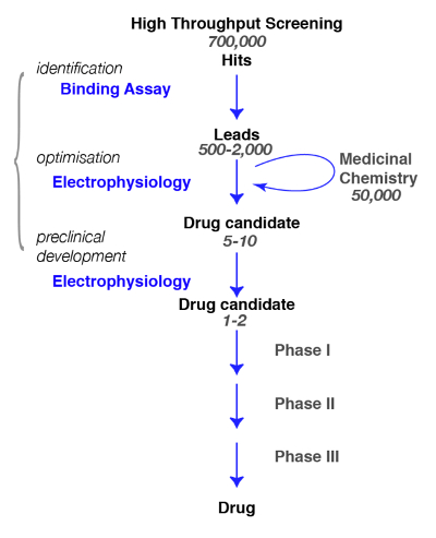
Figure 1: Screening strategy. A typical drug screening pathway begins with the high-throughput screening in which large libraries of compounds are screened for a specific target. Following the identification of the lead candidate, the work of medicinal chemistry begins. During this phase, chemists will study and refine the molecules by performing a structural modification to meet the desired criteria, such as target selectivity, brain penetrance, stability, degradation etc. During this crucial phase, it is essential to assess whether the chemical modifications have not altered the molecule properties and to refine for the best candidate. The following step is to identify a few promising compounds and bring them to the next steps which include safety, tolerance, etc. Note that electrophysiology is indicated as the functional assay but that other methods, including calcium fluorescence assays or voltage sensitive dyes, can be used as alternatives. These latter methods are also used in high-throughput assays as a substitution for binding assays. Please click here to view a larger version of this figure.
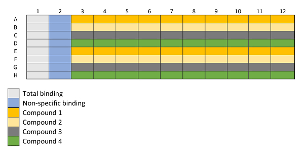
Figure 2: Layout of a 96-well plated utilized for binding experiments. Column 1 is used for total binding measurements and column 2 for non-specific binding measurements. Rows A–H are filled with 4 different compounds in increasing concentrations (columns 3–12), each compound in duplicates (i.e., Compound 1 in rows A and E, Compound 2 in rows B and F, etc.) represented in the layout with different colors. Please click here to view a larger version of this figure.
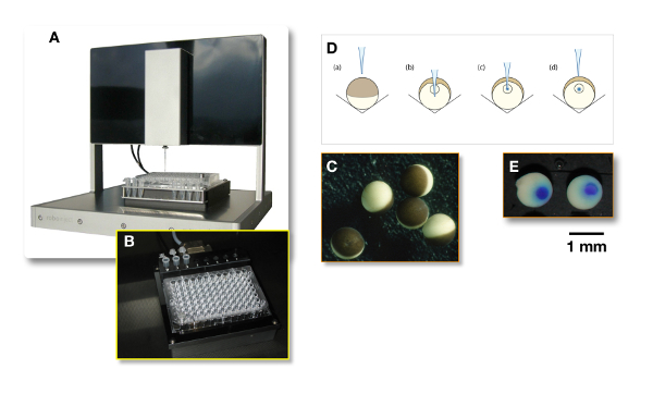
Figure 3: Microinjection using an automated system. (A) A precise XYZ system, in which a glass injection needle filled with the liquid containing the plasmid of interest, is automatically poked into the oocytes. (B) This panel shows the 96-well conical-bottom plate in which (C) the oocytes are automatically injected. (D) This panel illustrates the injection principle. For the nuclear injection, the needle penetrates the oocyte slightly deeper than the nucleus, as is shown in panel B. Then, the needle is withdrawn from the nucleus (see panel C) before the injection (see panel D). (E) To assess the quality of the injection, the needle can be filled with a dye and "cooked" oocytes can be cut in half. Please click here to view a larger version of this figure.
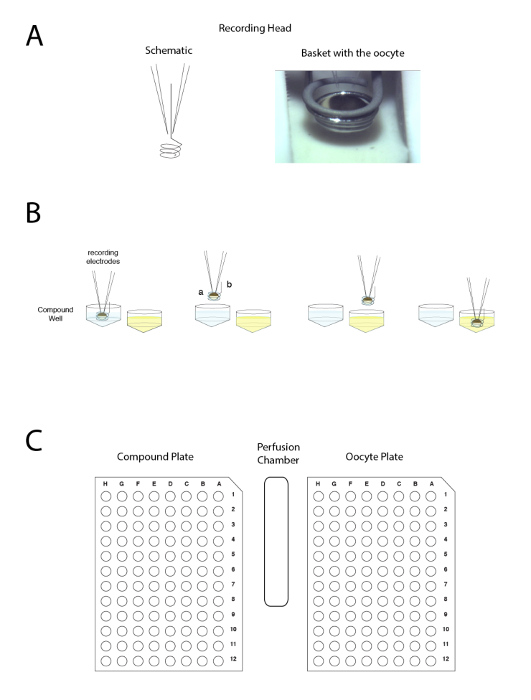
Figure 4: The automated two voltage-clamp electrode principle. The principle is based on moving the preparation between wells rather than applying the liquid in the perfusion. (A) The left-hand side of the panel represents the arrangement allowing the recording in a Xenopus oocyte with the two electrodes and the small basket that will maintain a liquid droplet around the preparation during the movement from one sample to another. A picture of the oocyte placed in the basket with the two electrodes is shown on the right-hand side. (B) This panel shows a schematic representation of the "upside down" electrophysiology recording principle. (C) This panel shows the disposition of the oocyte, compound plate, and wash station on the recording table. Please click here to view a larger version of this figure.
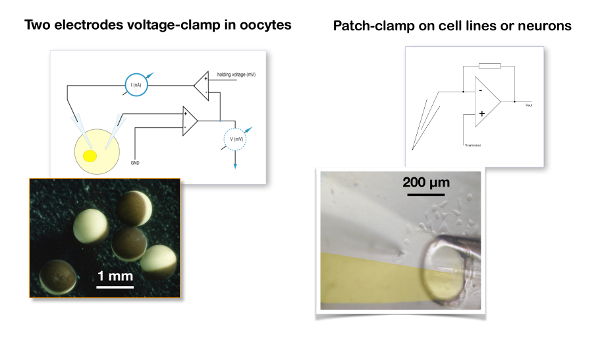
Figure 5: Two-electrode voltage clamp recording versus patch clamp. A typical two-electrode voltage clamp recording for oocytes (left panel) is compared to the patch clamp configuration used for a cell line (right panel). Note the difference in size between the oocytes which are about 1 mm in diameter versus the cells which are about 20 µm. In the two-electrode voltage clamp, the membrane potential of the oocyte is compared to the desired holding voltage and the signal difference is injected into the current electrode. In a patch clamp recording, it is assumed that the resistance of the patch clamp electrode is negligible versus the membrane resistance and, therefore, that the voltage imposed by the amplifier is faithfully fed to the cell membrane19. The picture illustrates a liquid filament perfusion in which the two channels of a theta tube () are filled with, on the one hand, a control solution and, on the other hand, with the solution containing the drug20,21. Please click here to view a larger version of this figure.
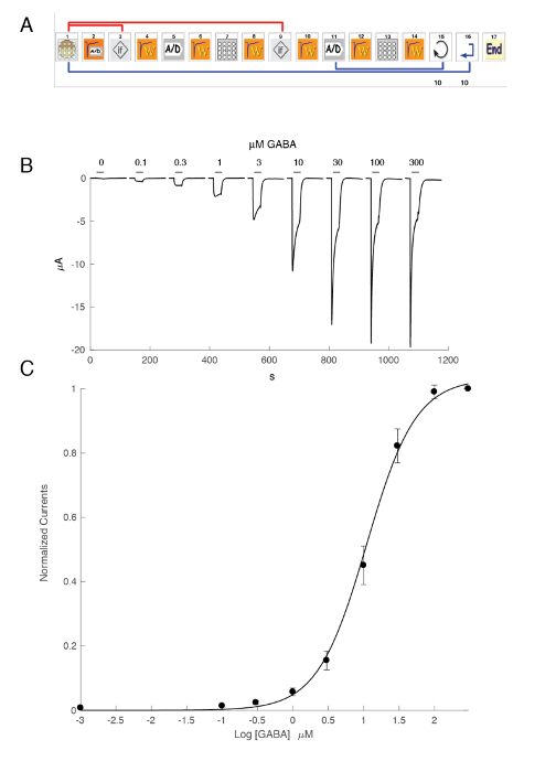
Figure 6: Concentration activation relationship at the human α5β3γ2 receptors. (A) The sequence controlling the automated system consists of a series of icons and sets the experimental protocol for the determination of the concentration activation relationship. In steps 1–3, as shown in this panel, the system loads the oocyte from the plate into the measuring basket. The leak current is measured in step 2 and, should this value exceed the desired criteria, the cell is automatically changed (step 3). Following a stabilization period (step 4), the oocyte response to a reference GABA concentration is measured (steps 5 – 8). Oocytes displaying currents larger than 1 µA are kept for the subsequent measurement. In steps 11–13, the cell is challenged by different concentrations of GABAA and the process repeats itself for the desired number of concentrations (step 14) and cells (step 15). (B) This panel shows the typical currents evoked by a series of brief GABA applications (30 s) applied in growing order. The timing of the compound application is indicated by the bars. (C) A plot of the peak inward current as a function of the logarithm of the GABA concentration yields the concentration activation curve that is readily fitted by the empirical Hill equation, with a continuous curve, an EC50 at about 11 µM, and a Hill coefficient of 1.3. Currents recorded in 8 cells were normalized to a unity for the maximal evoked response. The bars indicate the standard error of the mean. Please click here to view a larger version of this figure.
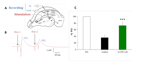
Figure 7: β-CCM, a GABAA NAM reduces paired-pulse inhibition in hippocampal slices. (A) This panel shows a schematic representation of a rat hippocampal slice. The Schaffer collaterals (Sch C) originating from the CA3 pyramidal cell axons project on the dendritic arborization of the CA1 pyramidal neurons. Micropipettes were placed in the stratum pyramidale (str pyramidale) to record population spikes (PS) and in the stratum radiatum (str radiatum) for dendritic recordings of field excitatory postsynaptic potentials (epsp). The stimulation electrode was placed within the Schaffer collaterals. (B) This panel shows PSs evoked by paired stimuli applied through the same stimulating electrode at a 20 ms interval. The population response to the second stimulus (PS2) is of smaller amplitude than that of the response to the first stimulus (PS1). (C) PSs were recorded in the absence (black bar) and presence of β-CCM, a non-selective GABAA receptor NAM (green bar). β-CCM enhanced the amplitude of the second PS2 by partially blocking any feed-forward GABAergic inhibition. The bars indicate the standard error of the mean and *** that data are highly significant with a p <0.01. Please click here to view a larger version of this figure.
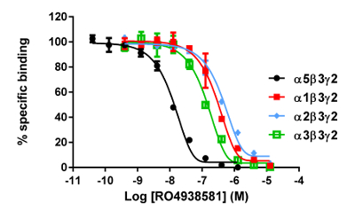
Figure 8: Typical binding results obtained in a competitive (inhibition or displacement) assay. Displacement binding curves are generated from which the IC50 and the Ki can be determined. IC50 is the concentration of a competing ligand which displaces 50% of the specific binding of the radioligand, and Ki (the inhibition constant for a drug) is the concentration of a competing ligand which would occupy 50% of the receptors if no radioligand were present. The Ki is calculated from the IC50 using the Cheng-Prusoff equation:

Please click here to view a larger version of this figure.
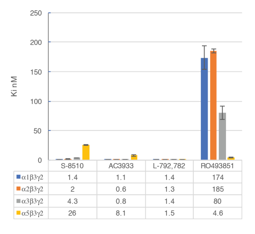
Figure 9: Competitive displacement binding was performed with ligands binding at the major GABAA receptor subtypes. Affinities (nM) were measured using a [3H]flumazenil-binding assay and membranes from HEK293 cells transiently transfected with different human GABAA receptor subunit combinations. The histogram representation clearly illustrates the differential sensitivity observed for the compound RO493851 with the lowest Ki at the α5β3γ2 receptors. Please click here to view a larger version of this figure.

Figure 10: Differential GABA sensitivity of receptors. A plot of the receptor GABA EC50 on a spider plot and a representation of the putative subunit composition provide efficient ways to compare the role of the different subunits. Note that the introduction of the γ2 subunits is associated with a reduction in the receptor sensitivity. Please click here to view a larger version of this figure.

Figure 11: Probing the effect of a modulator. (A) This panel illustrates the icon sequence used for controlling the automated system. Note that the two (A/D) icons correspond to the recording in the control (green) and during the modulator exposure (red). (B) This panel shows typical currents recorded in a cell expressing the GABAA receptor during such a sequence. To evaluate the effects of a modulator, a sequence of measuring first the response evoked by the exposure to a fixed concentration of GABA (green trace), followed by the exposure first to GABA and then to GABA plus the modulator (red trace), was conducted. Positioning the crosshair cursors (cyan and blue) delimits the measurements, and the blue cross indicates the maximal difference between the two recording conditions. The ratio between the control and modulator condition is automatically computed in the analysis software. Please click here to view a larger version of this figure.

Figure 12: Heat plot with three replicates. This panel shows a heat plot corresponding to three replicates of modulator effects obtained for 96 compounds at the human α5β3γ2 GABAA receptors. The ratios of the test response over the control ranging between 0.5 and 1.2 were considered as not significantly different from the control and are represented by a green dot. Ratios below 0.5 were considered as representing an inhibitory effect and are represented by blue dots. Ratios above 1.2 were considered as enhancing the response and are represented by red dots. Note the similitude in pattern between the three independent recordings. Please click here to view a larger version of this figure.
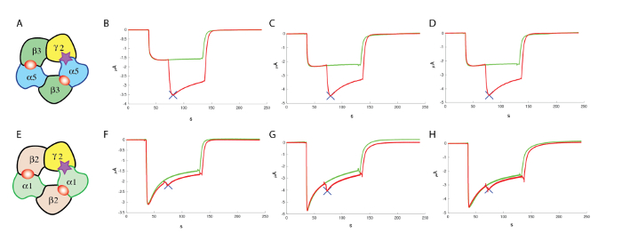
Figure 13: Counter screening at α1β2γ2. (A) This panel shows a representation of a putative subunit organization. The following panels show (B–D) an evaluation of the effects of a positive allosteric modulator at the human α5β3γ2 and (F–H) at α1β2γ2, using comparable concentrations of GABA and similar concentrations (100 µM) of the modulator, which highlight the specificity of the compound tested in these experiments. (E) This panel also shows a representation of a putative subunit organization. Please click here to view a larger version of this figure.
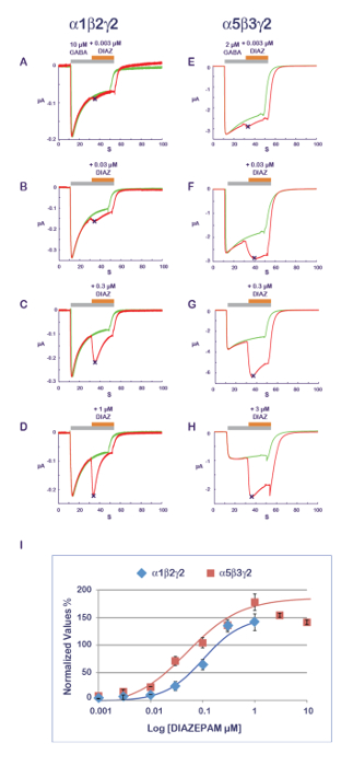
Figure 14: PAM sensitivity and receptor composition. The determination of the effects of a series of concentrations of diazepam effects (A–D) at α1β2γ2 and (E–H) α5β3γ2 receptors reveals almost a 10-fold difference in apparent affinity. Note also the influence of the subunit composition on the response time course with a faster desensitization at α1β2γ2 receptors (see, for example, panels D and H). Note that as the α1β2γ2 and α5β3γ2 receptors display different affinities for GABA (see also Figure 10), the concentration of agonist was adjusted between the two receptors to be in a comparable activation range. (I) This panel represents a plot of the fold increase in a current amplitude normalized to unity versus the control condition. Please click here to view a larger version of this figure.
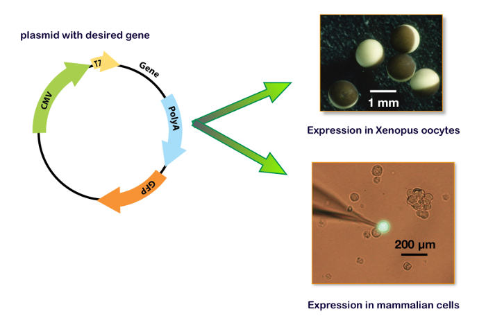
Figure 15: Expression plasmid including T7 and CMV promotor. These panels show the plasmid for the expression in a Xenopus oocyte (upper right panel) and in a cell line. The bottom right panel illustrates a typical HEK-293 cell transfected with a plasmid containing also the gene for a green fluorescent protein (GFP) with the patch-clamp recording electrode. Please click here to view a larger version of this figure.
Discussion
The development of novel compounds active at a ligand-gated ion channel such as the GABAA receptors requires the use of multiple approaches. Typically, the first step is often conducted using binding assays; however, such measurements are insufficient to characterize the physiological activity of the compound or its precise pharmacology. In particular, a compound that binds to a receptor may enhance or inhibit its function or even produce no functional effect (be silent) (i.e., bind to the receptor without modifying its function). Thus, a functional test is required for a full compound characterization.
Binding assays:
The main advantage of the binding assay is that it can be efficiently conducted on a large number of samples ranging up to several thousands and that it provides binding affinities for the active molecules. As described herein, the first step consists of establishing a method for the assessment of the desired receptor subtypes. Namely, while binding can be conducted on native receptors from fractions or entire brains, such a method will prevent the determination of the affinities at specific receptor subtypes. It is, therefore, necessary to use recombinant systems to screen molecules at the desired target. Nowadays, a transient or stable transfection of the desired receptor subunit cDNAs in cell lines offers an efficient and reliable method to express the receptor subtypes of interest (e.g., GABAA α5β3γ2). Traditional binding assays make use of radioligands, but nowadays techniques are available that avoid the inconvenience of handling radioactivity (e.g., quantitative fluorescence-based ligand-binding).
Functional expression in a host system:
To express genes in a host system, the coding sequence of interest must be inserted into a plasmid that contains the adequate promotors. Typically, for in vitro mRNA synthesis, the bacterial T7 or T6 promotors are used. For a cDNA expression, the transcription of the gene of interest must be regulated by a eukaryote promotor such as CMV (cytomegalovirus) or equivalent. Nowadays, several plasmids, including the two promotors (i.e., pUNIV, pCMV-6AC, psf-CMV/T7, pCI-neo, pcDNA), are available allowing either an in vitro synthesis of mRNA or a cDNA expression as shown in Figure 15. An expression of the GABAA receptors can be faithfully obtained either in cell lines or in Xenopus oocytes. The main advantages of the latter are the lack of an endogenous receptor expression, the simplicity of manipulations, and the availability of an automated system for micro-injections and recordings. The procedures described in this protocol illustrate the efficiency of the automated system which allows the injection of 96 oocytes in about 7 min and requires no micromanipulation skills. Remembering that a single ovary from a Xenopus contains between 10,000–30,000 oocytes, it is clear that a large number of cell measurements can be conducted on a single preparation. Moreover, as an expression can be conducted using cDNA injections, the same plasmids containing the genes of interest that are developed for the binding experiments can be used for a functional characterization without the need for further molecular biology manipulations.
Given its large size and high surface expression, a single oocyte yields a number of receptors that is approximately equivalent to the confluent cells in a 35 mm Petri dish. However, an oocytes preparation and injection represents a fraction of the cost of a cell line, as the experiments do not require a specific culture medium and sterile manipulations. The activation of a single GABAA channel yields a few picoamperes (10-12) and currents ranging up to tens of microampere (10-6) are easily recorded in a single oocyte, which confirms the concomitant activity of several millions of receptors during a single response.
A first step in the characterization of ligand-gated ion channels is often the determination of the apparent affinity of the receptors. The experiments that need to be conducted consist of applying a series of brief agonist test pulses and plotting the amplitude of the evoked current or, in certain cases, the area under the curve (AUC) as a function of the logarithm of the agonist concentration. As it is easily feasible to microinject different plasmid concentrations and ratio in the same batch of oocytes, this system of expression is particularly appropriate for such a characterization. Moreover, a batch-to-batch comparison revealed a high degree of stability for different EC50s. The influence of the subunit composition on the receptor's apparent affinity is readily visualized using a spider plot, as exemplified in Figure 10.
The results of the two-electrode voltage clamp obtained in Xenopus oocytes are often compared with recordings made using patch clamp electrodes. Whereas it would go beyond the scope of this work to go into a detailed comparison between these two systems, a few points can be examined. While a patch clamp in cells offers advantages for a biophysical characterization with a fast drug application, its requirements are more complex than those of the two-electrode recordings in Xenopus oocytes. A first and non-negligible difficulty is the expression of a given protein with the necessity of a cell culture, a transient or stable transfection, and the identification of the cells that are expressing the desired construct. In addition, it is indispensable to examine the possible contribution of the endogenous expression in the considered cell. Moreover, a patch clamp recording requires a skilled person to conduct the micromanipulation under a high-magnification microscope, while that person also needs to perform an adequate analysis during the experiment to assess, for example, the quality of the seal, the access resistance etc. In contrast, a two-electrode voltage clamp recording, especially one using an automated electrophysiological system, does not require any specific skills and can be conducted by laboratory technicians.
When acquiring an electrophysiological set-up, cost consideration is certainly an important factor that needs to be carefully analyzed. For example, while the cost of an automated system is relatively high, a closer comparison reveals that the installation of a complete electrophysiological rig includes buying equipment such as good micromanipulators, a binocular lens, an amplifier, a perfusion system, and an anti-vibration table, while also acquiring data and performing an analysis. A cost comparison between a two-electrode voltage clamp set-up versus a patch clamp set-up reveals even further discrepancies. Moreover, the automated system offers the advantage of fully automated equipment and runs unattended day and night.
The pharmacological properties of a compound are determined by its mode of action at the receptor. For example, competitive inhibitors are molecules that can enter the same binding pocket, or orthosteric site, as the agonist itself causes a competition. Non-competitive inhibitors are compounds that inhibit the receptors by interacting at another site and, in the case of a ligand-gated ion channel, that can enter and block the ionic pore, for example. It would go beyond the scope of this work to examine the different mechanisms of interaction, but further information can be obtained from a pharmacological textbook and/or from other work such as Bertrand and Bertrand's22.
In the case of allosteric modulators, the compound binds at a site that is distinct from the orthosteric site, but the presence of the molecule modifies the energy barrier between the active and other states. Positive allosteric modulators (PAMs) are compounds that reduce the energy barrier from the resting to the active state and, therefore, enhance the effect of the agonist. To characterize possible PAM effects, it is, therefore, necessary to determine if an exposure to the compound enhances the response to the agonist and, if so, at which concentration. The experiments presented in Figure 11 and Figure 14 illustrate protocols that can be successfully used for the characterization of PAMs at the GABAA receptors.
In some cases, exposure to the PAM alone might be sufficient to activate the receptors. Such activity can be determined by a slight modification of the experimental protocol presented here. Namely, instead of using a co-application of the modulator during the exposure to the GABA, the protocol can be modified for the application of first the compound alone and then in the presence of the GABA. A characterization of the direct agonist activity will be made by the determination of the amplitude of the response evoked by the compound itself and compared to the GABA-evoked current.
Experiments conducted in brain slices, such as illustrated in Figure 7, are used to confirm the compound activity at native receptors in a definite inhibitory circuit before going further in animal models and along the pathway towards clinical trials. The relatively simple data recording and analysis protocol allows the ranking of multiple compounds by evaluating their differential modulatory effect on PS amplitude. Non-specific effects of compounds which are not related to the GABA system may also be detected (e.g., when changes in the PS shape are observed). Direct, GABAergic neurotransmission can be assessed in these cases by measuring the effects of the compounds on inhibitory postsynaptic currents (IPSCs) using the whole-cell patch clamp technique8.
Disclosures
The authors have nothing to disclose.
Acknowledgements
The authors thank Judith Lengyel, Maria Karg, Grégoire Friz, Rachel Haab, and Marie Claire Pflimlin from Roche and Tifany Schaer and Deborah Paolucci from HiQScreen for their excellent technical assistance.
Materials
| General equipment | |||
| 96 well cell harvester -(Filtermate 196) | Packard | To filter membranes with bound radioligand | |
| Microtiter plate liquid scintillation counter (Top Count NXT) | Packard | Microplate Scintillation and Luminescence counter | |
| Vial liquid scintillation counter (Beta-Couter 2500 TR) | Packard | Vial Scintillation and Luminescence counter | |
| Liquid handler (Biomek 2000) | Beckman coulter | To prepare compound dilutions | |
| Vortex (Vortex Genie 2) | Scientific industries Inc. | To mix compound stock solutions | |
| Tissue homogenizer (Polytron PT1200E) | Kinematica AG | To resuspend the membrane preparations | |
| XLfit5 software | Microsoft Excel add-on by IDBS |
Curve fitting software | |
| Smart Pull | UniPix | – | Electrode Puller |
| RoboInject | MultiChannel Systems | – | Automated Injection (Xenopus Oocytes) |
| HiClamp | MultiChannel Systems | – | Automated Voltage Clamp (Xenopus Ooocytes) |
| DataMining | MultiChannel Systems | – | Data Analysis Software |
| DataMerger | MultiChannel Systems | – | Data Processing Software |
| Digidata 1550 | Molecular Devices | Low noise data acquisition system | |
| CyberAmp 380 or equivalent | Axon Instruments | Programmable Signal Conditioner | |
| pClamp program suite | Molecular Devices | Software for data acquisition and analysis software | |
| Antivibraton table | TMC | To avoid microelectrode vibrations | |
| Patchstar Micromanipulators | Scientifica | To accurately position microelectrodes in brain slices | |
| Faraday Cage | Sutter Instruments | To isolate recordings from noise | |
| McIlwain Tissue Chopper | Campden Instruments LTD | To prepare brain slices | |
| Borosilicate glass micropipette | Warner Instruments | GC150TF-10 | To record extracellular potentials in brain slices |
| Twisted pair, platinum iridium wires stimulation electrode | World Precision Instruments | To stimulate the brain slices with current | |
| Stimulus generator for current and voltage driven stimulation | MultiChannel Systems | STG4000 | Delivers the current to the stimulation electrode |
| Plasticware | |||
| Microtiter plate round bottom | Corning | #3365 | Used for the binding assay |
| GF/C glassfibre filter-bottom 96-well microplate with 1.2µm poresize, for cell harvesting assays using a vacuum manifoldwell filter | Packard | #6005174 | used for the binding assay |
| 50 mL Tubes | Falcon | #352070 | used for the binding assay |
| Safe-lock tubes 1.5 mL | Eppendorf | #0030 120086 | used for the binding assay |
| Safe-lock tubes 2 mL | Eppendorf | #0030 120094 | used for the binding assay |
| Shipping tubes 180ml | Semadeni Europe AG | #3722 | used for the binding assay |
| Pony vial Polyethylene 6ml | Perkin Elmer | #6013329 | used for the binding assay |
| Top Seal | Perkin Elmer | #60051859 | used for the binding assay |
| Spinner Flask | Bellco | BELLCO # 1965-00100 | Spinner Flask |
| 96 Well Plate (Conical) | Thermo Scientific Milian | 56368 | Injection plate for the oocytes |
| 96 Well Plate (Flat bottom) | Corning (Vitaris Switzerland) | 3364-cor | Compound Plate for the HiClamp |
| Glass capillary | Hilgenberg (Germany) | – | borosilicate glass 1.2 O.D. 0.76 I.D. with filament |
| RNA preparation | |||
| Ambion mMessage mMachine | Thermo Fisher Scientific | for the in vitro synthesis | |
| Chemicals | |||
| Assay buffer: KCl 5 mM; CaCl2 1.25 mM; MgCl2 1.25 mM; NaCl 120 mM; Tris 15 mM pH adjust with HCl to 7.4; store up to 3 months at 4°C. | Used for binding assay | ||
| Washing buffer: Tris 50mM -HCl pH 7.4; store at 4°C. | Used for binding assay | ||
| Stock solution of test compounds 10mM in DMSO | Used for binding assay | ||
| Flumazenil (RO0151788) 10mM in DMSO | Used for binding assay | ||
| Diazepam 4mM in DMSO | Used for binding assay | ||
| [3H]-Flumazenil 60-85 Ci/mmol in Ethanol; store at -20°C | Used for binding assay | ||
| Microscint 40 | Packard | #6013641 | Used for binding assay |
| Ultima Gold | Perkin Elmer | #6013329 | Used for binding assay |
| MS-222 | Sigma | Sigma # A5040 | MS-222 |
| AB/AM | Sigma | Sigma # A5955 | antibiotics / antimycotics |
| Collagenase | Sigma | Sigma # C1030 | Collagenase Type I |
| Rnase | Sigma | Sigma # R2020-250 mL | RNaseZAP |
| EndoFree Plasmid maxi Kit | Qiagen | Qiagen # 12362 | |
| Salts for artificial cerebrospinal fluid (NaCl, KCl, etc.) | Sigma | ||
| Membranes | |||
| Frozen membrane preparations from transient or stably transfected HEK293 overexpressing different human GABAA receptor subtypes: α1β3γ2, α2β3γ2, α3β3γ2, α5β3γ2. See Ballard et al 2009 for detailed methods. | Used for binding assay |
References
- Rudolph, U., Knoflach, F. Beyond classical benzodiazepines: novel therapeutic potential of GABAA receptor subtypes. Nature Reviews Drug Discovery. 10, 685-697 (2011).
- Sieghart, W. Structure and pharmacology of g-aminobutyric acidA receptor subtypes. Pharmacological Reviews. 47, 181-234 (1995).
- Liu, J., et al. A high-throughput functional assay for characterization of g-aminobutyric acidA channel modulators using cryopreserved transiently transfected cells. ASSAY and Drug Development Technologies. 6, 781-786 (2008).
- Mennerick, S., et al. Diverse voltage-sensitive dyes modulate GABAA receptor function. Journal of Neuroscience. 30, 2871-2879 (2010).
- Hevers, W., Luddens, H. The diversity of GABAA receptors. Pharmacological and electrophysiological properties of GABAA channel subtypes. Molecular Neurobiology. 18, 35-86 (1998).
- Macdonald, R. L., Olsen, R. W. GABAA receptor channels. Annual Review of Neuroscience. 17, 569-602 (1994).
- Kemp, J. A., Marshall, G. R., Wong, E. H., Woodruff, G. N. The affinities, potencies and efficacies of some benzodiazepine-receptor agonists, antagonists and inverse-agonists at rat hippocampal GABAA-receptors. British Journal of Pharmacology. 91, 601-608 (1987).
- Prenosil, G. A., et al. Specific subtypes of GABAA receptors mediate phasic and tonic forms of inhibition in hippocampal pyramidal neurons. Journal of Neurophysiology. 96, 846-857 (2006).
- Ballard, T. M., et al. RO4938581, a novel cognitive enhancer acting at GABAA a5 subunit-containing receptors. Psychopharmacology. 202, 207-223 (2009).
- Knoflach, F., Hernandez, M. C., Bertrand, D. GABAA receptor-mediated neurotransmission: Not so simple after all. Biochemical Pharmacology. 115, 10-17 (2016).
- Gielen, M. C., Lumb, M. J., Smart, T. G. Benzodiazepines modulate GABAA receptors by regulating the preactivation step after GABA binding. Journal of Neuroscience. 32, 5707-5715 (2012).
- Bergmann, R., Kongsbak, K., Sorensen, P. L., Sander, T., Balle, T. A unified model of the GABAA receptor comprising agonist and benzodiazepine binding sites. PLoS One. 8, 52323 (2013).
- Richter, L., et al. Diazepam-bound GABAA receptor models identify new benzodiazepine binding-site ligands. Nature Chemical Biology. 8, 455-464 (2012).
- Rudolph, U., Crestani, F., Mohler, H. GABAA receptor subtypes: dissecting their pharmacological functions. Trends in Pharmacological Sciences. 22, 188-194 (2001).
- Wisden, W., Seeburg, P. H. GABAA receptor channels: from subunits to functional entities. Current Opinion in Neurobiology. 2, 263-269 (1992).
- Davies, C. H., Davies, S. N., Collingridge, G. L. Paired-pulse depression of monosynaptic GABA-mediated inhibitory postsynaptic responses in rat hippocampus. The Journal of Physiology. 424, 513-531 (1990).
- Karnup, S., Stelzer, A. Temporal overlap of excitatory and inhibitory afferent input in guinea-pig CA1 pyramidal cells. The Journal of Physiology. 516, 485-504 (1999).
- Turner, D. A. Feed-forward inhibitory potentials and excitatory interactions in guinea-pig hippocampal pyramidal cells. The Journal of Physiology. 422, 333-350 (1990).
- Hamill, O. P., Marty, A., Neher, E., Sakmann, B., Sigworth, F. J. Improved patch-clamp techniques for high-resolution current recording from cells and cell-free membrane patches. Pflügers Archiv. 391, 85-100 (1981).
- Adelsberger, H., Brunswieck, S., Dudel, J. Block by picrotoxin of a GABAergic chloride channel expressed on crayfish muscle after axotomy. European Journal of Neuroscience. 10, 179-187 (1998).
- Hapfelmeier, G., et al. Isoflurane slows inactivation kinetics of rat recombinant a1b2g2L GABAA receptors: enhancement of GABAergic transmission despite an open-channel block. Neuroscience Letters. 307, 97-100 (2001).
- Bertrand, S., Bertrand, D. Overview of electrophysiological characterization of neuronal nicotinic acetylcholine receptors. Current Protocols in Pharmacology. , 17 (2004).

