Equipment Setup and Artifact Removal for Simultaneous Electroencephalogram and Functional Magnetic Resonance Imaging for Clinical Review in Epilepsy
Summary
This article details simultaneous electroencephalogram and functional magnetic resonance imaging (EEG-fMRI) recording procedures that can be used in both clinical and research settings. EEG processing procedures to remove imaging artifacts for clinical review are also included. This study focuses on the example of epilepsy during the interictal period.
Abstract
Simultaneous electroencephalogram and functional magnetic resonance imaging (EEG-fMRI) is a unique combined technique that provides synergy in the understanding and localization of seizure onset in epilepsy. However, reported experimental protocols for EEG-fMRI recordings fail to address details about conducting such procedures on epilepsy patients. In addition, these protocols are limited solely to research settings. To fill the gap between patient monitoring in an epilepsy monitoring unit (EMU) and conducting research with an epilepsy patient, we introduce a unique EEG-fMRI recording protocol of epilepsy during the interictal period. The use of an MR conditional electrode set, which can also be used in the EMU for a simultaneous scalp EEG and video recording, allows an easy transition of EEG recordings from the EMU to the scanning room for concurrent EEG-fMRI recordings. Details on the recording procedures using this specific MR conditional electrode set are provided. In addition, the study explains step-by-step EEG processing procedures to remove the imaging artifacts, which can then be used for clinical review. This experimental protocol promotes an amendment to the conventional EEG-fMRI recording for enhanced applicability in both clinical (i.e., EMU) and research settings. Furthermore, this protocol provides the potential to expand this modality to postictal EEG-fMRI recordings in the clinical setting.
Introduction
Epilepsy afflicts nearly 70 million people worldwide1. As many as one out of every 150 people with poorly controlled epilepsy succumb to a sudden unexpected death in epilepsy (SUDEP) every year. Furthermore, roughly 30%-40% of epilepsy cases are refractory to medical management2. Neurosurgical treatment in the form of resection, disconnection, or neuromodulation can be a life-changing and life-saving measure for patients with refractory epilepsy.
Simultaneous electroencephalogram and functional magnetic resonance imaging (EEG-fMRI) is a unique combined technique that measures brain activities noninvasively, and has provided benefits for understanding and localizing seizure onset in epilepsy3,4,5,6. Scalp EEGs can be used to lateralize and localize seizure onset zones, but they have relatively poor spatial resolution due to limited capabilities with respect to assessing deep epileptogenic sources. While fMRI has good spatial resolution throughout the brain, including deep regions, fMRI alone is not specific to seizures. However, scalp EEGs can inform the interpretation of blood oxygen level-dependent (BOLD) activation or deactivation areas in fMRI, thereby producing an fMRI technique that is specific to epilepsy. Thus, the implementation of simultaneous EEG-fMRI can be used to map spatiotemporal processes relevant to localizing both the 'where' and 'when' of epileptic events.
Explanations of how to conduct simultaneous EEG-fMRI are provided in the previous studies7,8,9,10. However, EEG-fMRI has been underutilized in epilepsy, especially in clinical settings. There exists a study that provides a general procedure for EEG-fMRI recordings, background, and examples of possible EEG analysis7. Also, a study emphasizing hypnotic induction along with temperature measures in simultaneous EEG-fMRI recordings has been conducted8. Furthermore, an expanded EEG-fMRI study to introduce a spatiotemporal and fMRI-constrained EEG source imaging method has been proposed9,10. In addition, the use of a carbon wire loop to effectively remove artifacts from EEG-fMRI has been considered10. However, all these studies fail to address challenges in conducting EEG-fMRI studies in a clinical research setting. In particular, the use of the EEG cap restricts the feasibility of these protocols in clinical settings, and details about patient management are also missing. In this study, we provide an EEG-fMRI recording protocol that can be used in both clinical and research settings for patients with epilepsy. This unique protocol allows an easy patient transition from an epilepsy monitoring unit (EMU) to the scanning room. In addition, the protocol provides the potential to expand its application to postictal period recordings with epilepsy patients. For EEG-fMRI, post-processing is a crucial step in removing artifacts caused by MRI gradients and physiological artifacts, such as those related to heartbeat. Thus, we also provide step-by-step procedures to remove EEG artifacts using a standard template removal method11 for clinical review.
Protocol
This study was performed in compliance with Protocol #62050, approved by the Institutional Review Board at the University of Kentucky (UK).
1. Subject recruitment
- Inclusion criteria
NOTE: All of the following criteria must be met.- Include subjects diagnosed with refractory focal epilepsy and eligible for epilepsy surgery evaluation.
- Include subjects who are between 18-60 years of age.
- Include female subjects with childbearing potential if they use a contraceptive method. Include female subjects without childbearing potential (postmenopausal for at least 2 years, bilateral oophorectomy or tubal ligation, complete hysterectomy).
NOTE: Per standard of care, a pregnancy test is performed for women of childbearing potential once admitted to the EMU. - Include subjects scheduled for admission to the EMU with a diagnosis of refractory focal epilepsy or for seizure characterization.
- Exclusion criteria
- Exclude subjects who have severe claustrophobia.
- Exclude subjects with implanted medical devices or embedded metal which would normally disqualify them from having an MRI, which is routinely checked by the MR technologist prior to any scan.
- Exclude subjects who are pregnant or lactating.
- Exclude subjects with any known medical or psychiatric condition that, in the investigator's opinion, could jeopardize or would compromise the subject's ability to participate in this study, or would impair reliable participation in the study.
NOTE: Once the patient is admitted to the EMU, after the patient's agreement on the consent form to participate in this study, the following steps will be followed.
2. Electrode placement
- Mark electrode positions on the patient's scalp, based on the 10-20 system.
NOTE: Figure 1 shows one selection of 32 electrodes.- Measure and note the patient's head center line of the scalp by placing a measuring tape from the nasion to the inion by passing the top center of the head (Measure A: sagittal plane).
- Mark 50% of Measure A from the nasion to the inion. This mark indicates the electrode's Cz location.
- Mark 10% of Measure A from the nasion to the indicated Cz. This mark indicates the electrode's Fpz location.
- Mark 10% of Measure A from the inion to the indicated Cz. This mark indicates the electrode's Oz location.
- Mark 20% of Measure A from the indicated Cz to Fpz. This mark indicates the electrode's Fz location.
- Mark 20% of Measure A from the indicated Cz to Oz. This mark indicates the electrode's Pz location.
- Measure and note the patient's head from the left preauricular point to the right preauricular point by passing the top center of the head (Measure B: coronal plane).
- Mark 50% of Measure B and make sure this location is overlapped with the indicated Cz location.
- Mark 10% of Measure B from the left preauricular point to Cz. This mark indicates the electrode's T3 location.
- Mark 10% of Measure B from the right preauricular point to Cz. This mark indicates the electrode's T4 location.
- Mark 20% of Measure B from the indicated Cz to T3. This mark indicates the electrode's C3 location.
- Mark 20% of Measure B from the indicated Cz to T4. This mark indicates the electrode's C4 location.
- Measure and note the circumference of the patient's head by passing through the marked Fpz and Oz (Measure C: transverse plane).
- Mark 10% of Measure C left and right from Fpz. These marks indicate the electrode's Fp1 and Fp2 locations, respectively.
- Mark 10% of Measure C left and right from Oz. These marks indicate the electrode's O1 and O2 locations, respectively.
- Mark 20% of Measure C left from Fp1 and right from Fp2. These marks indicate the electrode's F7 and F8 locations, respectively.
- Measure and note the distance from F7 and F8 in the coronal plane (Measure D: coronal plane).
- Mark 50% of Measure D, and make sure the previously indicated Fz is overlapped.
- Mark 25% of Measure D from F7 toward Fz, and from F8 to Fz. These marks indicate the electrode's F3 and F4 locations, respectively.
- Measure the distance from the nasion to the inion passing through Fp1 and O1. Ensure 50% of the measure overlaps with the previously indicated C3.
- Measure the distance from the nasion to the inion passing through Fp2 and O2. Ensure 50% of the measure overlaps with the previously indicated C4.
NOTE: In the same manner, electrode positions on the temporal and parietal lobes can be marked, including T5, P3, P4, and T6. In addition, any additional electrode locations, such as TP9, TP10, FT9, and FT10, can be marked based on the relative distance from the 10-20 system's electrode distributions. The number of electrodes and their distributions can be determined based on the prospective analysis and research focus.
- Clean the patient's scalp using skin prep gel on gauze.
- Place conductive paste on one electrode cup. Place the electrode on the patient's scalp following the channel name on the electrode's cable.
NOTE: For simultaneous EEG-fMRI recording, it is required to use MR conditional electrodes, and Food and Drug Administration (FDA)-approved electrodes are suggested at the EMU. - Repeat placing the gel and electrodes on the patient's scalp (step 2.3) for all electrodes (Figure 2A).
NOTE: The cables connected to the MR conditional electrodes are relatively short to the connecting junction to minimize the MR artifacts. Therefore, when placing the electrodes, consider the electrode positions and carefully place them so that the cables can be well organized. In addition, make sure there are no loops on the wires, since they can potentially produce heat and burns inside the scanner. - Adhere all electrodes to the patient's scalp using glue on gauze. Arrange all the electrode cables and place the cable junction far from the scalp by placing pads of gauze on the center of the subject's head (Figure 2B, red arrows).
NOTE: This is a critical step to avoid imaging artifacts. - Wrap all the cable junctions with self-adhesive bandage wrap (blue ovals in Figure 2B).
NOTE: This step is suggested to secure the connections during the recording. - Place an elastic head cover to secure all the electrodes. Connect the harness, which is connected to the electrodes, to the amplifier. Begin monitoring their EEG synchronously with video recordings.
3. EEG-fMRI recording
NOTE: For the EEG-fMRI recording, the MR conditional EEG recording system is used along with the MR conditional electrodes placed at the beginning of EMU admission.
- In the monitoring room, connect the USB 2 adapter to the Triggerbox kit with a cable (thick white cable in Figure 3A).
NOTE: The USB 2 adapter allows to interface other hardware with a computer, and the Triggerbox kit is employed to manipulate the trigger signal generated from the scanner to be detected in the EEG recording software. - Connect the Syncbox to the USB 2 adapter with a cable (thick black cable in Figure 3B).
NOTE: The role of the Syncbox is to synchronize the clock signals from the amplifier and the scanner's gradient switching system. - In the monitoring room, connect one end of the fiber optic cable to the Syncbox (Figure 3C left), and pass another end through a tunnel connected to the scanning room.
- Connect a USB port cable from the USB 2 adapter to the recording computer (star mark in Figure 3B). Connect a USB port cable from the Syncbox to the recording computer (star mark in Figure 3C). Connect a USB port cable from the Triggerbox to the recording computer (star mark in Figure 3D). Connect the software license dongle to the recording computer.
NOTE: There are in total four USB ports that will be used. Having a multi-USB port can be helpful in managing them all. - Set up the EEG recording amplifier along with the MR-sled kit inside the scanner.
CAUTION: Any metal or MR-sensitive components must be removed from the experimenters. It is required for the experimenters to complete appropriate training to conduct recordings in the MRI scanning room.
NOTE: It is recommended to fully charge the amplifier battery prior to conducting the recording. - Connect the end of the fiber optic cable in the scanning room to the back of the amplifier (Figure 4D) and turn on the amplifier.
NOTE: The other end of the fiber optic cable is connected to the Syncbox in the monitoring room. - When the equipment setup is complete, open the EEG recording software by clicking the software icon on the computer screen. Create a workspace in the recording software by clicking the New Workspace menu under the File tab in the top left of the window.
- Set a folder path where the new data will be stored by clicking the 열람 button.
- Insert the data name in a blank box for Prefix and specify the numbering index by inserting a numeral in the black boxes for Min. Counter Size [digits] and Current Number.
- After confirming that the file name is correctly displayed under Next Resulting Filename, click Next.
- Scan the amplifier by clicking the Scan for Amplifier button in the top left of the created window. Set up appropriate parameters, including sampling rates and low and high cut-off frequencies for recording by selecting the appropriate options listed for Sampling Rate, Low Cutoff, and High Cutoff (see Figure 5).
NOTE: The Sampling Rate is set to 5,000 Hz to sufficiently sample the gradient artifacts from the scanner. A Low Cutoff of 10 s is inserted to prevent direct current (DC) saturation (the time unit is used in the recorder software), and a High Cutoff of 250 Hz is set to limit the gradient artifact amplitude before entering the analog to digital converter. - Set the scanner parameters for the fMRI.
NOTE: A possible resting state fMRI BOLD acquisition setting is an echo-planar sequence (TR/TE = 1360/29 ms, flip angle = 65, 54 slices covering the entire brain, field of view = 260 mm x 260 mm, resolution = 2.5 mm isotropic voxels). The details of the fMRI settings can be varied depending on the objective of the recording. - Switch off the scanner helium pump to further reduce the introduction of artifacts into the EEG signal.
NOTE: Turning off the helium pump can result in liquid helium loss or shield temperature increases. Thus, it is strongly recommended to check with the scanner vendor to verify if turning off the helium compressor is not overly detrimental to their MRI scanning system. - Transfer the patient to the scanning waiting room. Explain the recording procedure to the patient.
NOTE: It is recommended that all the recording equipment setup is completed before the patient's arrival. - Clean the patient's back, right below the patient's left shoulder, where the electrocardiogram (ECG) lead will be placed. Apply an abrasive electrolyte gel on the ECG lead and place it on the left back side of the patient.
NOTE: The length of this cable is short, so when placing the ECG lead, do not pull strongly or put it too low on the back; approximately 5 cm below the shoulder is acceptable. The ECG lead is placed on the back to minimize moving artifacts. - Apply adhesive tape around the ECG lead and cable to minimize scanning artifacts during the recording. Disconnect the EEG harness and connect the EEG cable junctions to the interface box (Figure 4B).
- Transport the patient to the scanning room. Lay the patient down onto the scanning table with the head in the open bottom half of the head coil.
CAUTION: Any metal or MR sensitive components must be removed from the subject.
NOTE: Support the patient's back when lying down. - Apply earplugs to help reduce the scanner's noise. Apply a cushion around the patient's head to minimize head movement artifacts.
- Connect the top half of the head coil to close the "bird cage" coil around the patient's head. Adjust the bed height. Connect the interface box to the amplifier (Figure 4C).
NOTE: Adhesive tape is also applied to the cables from the interface box to minimize scanning artifacts (white wrap in Figure 4B). - Place the MR-safe sandbags around the cables to minimize the MR artifacts during the recording (Figure 4C). Once all the settings in the scanning room are complete, move to the monitoring room.
- Communicate with the patient through a microphone in the monitoring room, explaining that additional steps for setting the software settings are being carried out.
NOTE: The experimenters can communicate through built-in speakers in the scanning room and a microphone in the monitoring room. - Check the impedance of the EEG electrodes by clicking on the Impedance Check button in the top left of the recording software window opened on the computer. Confirm with the patient that they are ready for the recording.
NOTE: During the recording, experimenters monitor the patient's condition through a video camera in the scanning room and communicate through the microphone in the monitoring room. - Start the EEG recording by clicking on the Play button in the top left of the recording software. Run the fMRI acquisition scan.
CAUTION: In any case when the patient reports discomfort due to the recording environment, including noise, the experimenter should stop the recording procedure.
4. EEG artifact removal
NOTE: The following descriptions provide detailed steps on how to remove the scanner artifacts on the EEG data obtained from the simultaneous EEG-fMRI recordings. Figure 6 displays the processing pipeline with representative examples.
- Open the EEG analysis software.
- Apply MR artifact correction.
- Click on the Transformations > Special Signal Processing > MR Correction tab. When a small window is generated, select Use Markers, choose a trigger signal from the scanner, and click Next.
NOTE: This step indicates a trigger signal from the scanner and uses it as a reference to remove the MR artifacts. - Select the Interleaved and Based on Time options, insert the time information of the trigger signal, and click on Next.
NOTE: In the acquired data, V1 is the trigger signal, and the following values can be inserted based on the V1 trigger intervals: start [ms]: -2; end [ms]: 1,358; and duration [ms]: 1,360. The label of the trigger signal and its detailed setting can be varied depending on the scanner's configuration. - In the following window, check Enable Baseline Correction for Average and uncheck Compute Baseline Over the Whole Artifact. Insert the Start [ms] and End [ms] values. Select Use Sliding Average Calculation.
NOTE: This allows one to correct the baseline based on a sliding window. - Insert Total Number of Intervals for Sliding Average, check Common Use of All Channels for bad Intervals and Correction, and click on Next.
NOTE: Total Number of Intervals for Sliding Average can be 21. - Select Use All Channels for Correction and click Next.
- Check Do Downsampling and choose 500 for New Frequency [Hz]. Check Apply Lowpass Filter and select Use FIR Filter, insert 70 for Cut-off Frequency [Hz], and then click on Next.
- Once all the settings are completed, select one Store Corrected Data option, and then click on Finish.
NOTE: Store Data Uncompressed in History File can be selected as a Store Corrected Data option. Different options may be considered, depending on the purpose. After clicking Finish, a small Scanner Artifact Correction window will appear in the middle, showing the processing status. This MR correction process may take some time to complete, depending on the EEG data size.
- Click on the Transformations > Special Signal Processing > MR Correction tab. When a small window is generated, select Use Markers, choose a trigger signal from the scanner, and click Next.
- Apply DC removal by a high-pass filter. Click on the Transformation > Data Filtering > IIR Filters tab. On a newly generated window, check Enabled under Low Cutoff. Insert a cutoff Frequency [Hz] of 0.5, choose the filter Order as 2, and then click on OK.
- Remove cardioballistic artifacts.
- Click on the Transformations > Special Signal Processing > CB Correction tab. On the window that subsequently opens, select Use Peak Detection and check Semiautomatic Mode.
- Under the Search Pulse Template section, insert Start[s] as 60 and Length[s] as 20. Check Mark Found Template and make sure the appropriate ECG channel is chosen.
- Insert proper parameters for Pulse Rate and Correlation and Amplitude, insert R for Mark Pulses with R-Peak Markers, and then click on Next.
NOTE: The suggested value for Pulse Rate [ms] is 1000 ± 400 and Pulse Rate [bpm] is a minimum of 43 and a maximum of 100. The specific Pulse Rate values depend on the subject's ECG ranges. In addition, Correlation Trigger Level can be set as 0.6 and Amplitude Trigger Level as a minimum of 0.3 and a maximum of 1.4. - Check Use Whole Data to Compute the Time Delay. Insert Total Number of Pulse Intervals Used for Average.
NOTE: Total Number of Pulse Intervals Used for Average can be set as 21. - Under Correct Following Channels, move all the EEG channels to the right column except the ECG channel, and then click Next.
- On the next page, select one Store Corrected Data option as preferred. Click on Finish.
NOTE: Once Finish is clicked, a CB Correction-Interactive Mode window will appear on the right side of the software. - Slide over the time axis at the bottom of the Navigation Bar and check where the base template ECG is highlighted with a blue shaded box. Confirm the base template of the ECG is correctly marked.
NOTE: By double-clicking the ECG channel name, only the ECG channel will be displayed for review. Consider a manual adjustment of the peak or the interval as needed. In the CB Correction-Interactive Mode window on the right side of the software, ECGs with abnormal patterns are listed in sequential order in a table format. These are indicated in the ECG trace as red vertical lines. - In the CB Correction-Interactive Mode window, check each marked ECG by double-clicking on its corresponding row in the table. Adjust the detected peak locations, as needed, by moving the red vertical lines. Once all the detected ECGs are reviewed, click on Finish.
NOTE: The channel initially contains only red and green markers. The green markers indicate good detections, while the red markers indicate potential pulse peaks that do not meet all conditions required. The red markers change to yellow after modifying them manually. When correcting the abnormal ECGs, it is important to consider that each peak location and the time interval of each ECG should be consistent.
- Apply powerline and alternating current (AC) noise removal by a notch filter. Click on the Transformation > Data Filtering > IIR Filters tab. In the window that opens, check Notch Enabled, select Frequency [Hz], and then click on OK.
NOTE: For the frequency selection, either 50 or 60 Hz can be selected depending on the country where the recording is conducted. The notch filter is applied at the last step to be beneficial for the ECG detections, and this filter application provides the convenience of clinical EEG review.
Representative Results
When a patient is admitted to the EMU, a simultaneous scalp EEG and video are recorded. One purpose of the EEG monitoring by a neurologist is to evaluate for epileptiform discharges, which can potentially inform the localization of the seizure onset. When extraordinary dynamics of specific EEG channels are distinguished, the electrode locations can be associated with seizure localization. During the interictal period, interictal epileptiform discharges (IEDs), including spikes and sharp waves, are traditionally considered as markers of areas of epileptogenicity. Furthermore, the obtained recordings of interictal EEG-fMRI data can be advantageous to understand and localize the seizures. To validate this EEG-fMRI recording and EEG processing protocol, we evaluate the quality of the EEG by comparing the postprocessed EEG to the one from the EMU, and we confirm that the same distinguishable EEG characteristic is observed in both cases.
Focal delta slow activity is typically suggestive of an underlying brain structural lesion or an area where the neurons are not functioning as expected, which is often observed after strokes, head injuries, brain infections, or dementia. However, it is not uncommon for patients with focal epilepsy to demonstrate focal delta activity near or at the site of their epileptogenic zone. In addition, although focal delta activity is less specific than IEDs, it can specify localized structural pathology corresponding to seizure onset in epilepsy12. Furthermore, focal interictal slow waves in EEGs correspond to focal BOLD activation on fMRI that matches the epileptogenic area in patients with partial epilepsy13.
It is notable that, in temporal lobe onset epilepsy, a type of delta activity called temporal intermittent rhythmic delta (TIRDA) is sometimes present, and it is considered an IED equivalent14. On the contrary, temporal intermittent polymorphic delta (TIPDA) is not considered an IED equivalent15. In the processed EEG data, clear focal left temporal slow waves (TIPDA) are present, which is observed from the EEG recorded at the EMU (Figure 7). Although this delta activity is not IED equivalent, it suggests left temporal neuronal dysfunction.
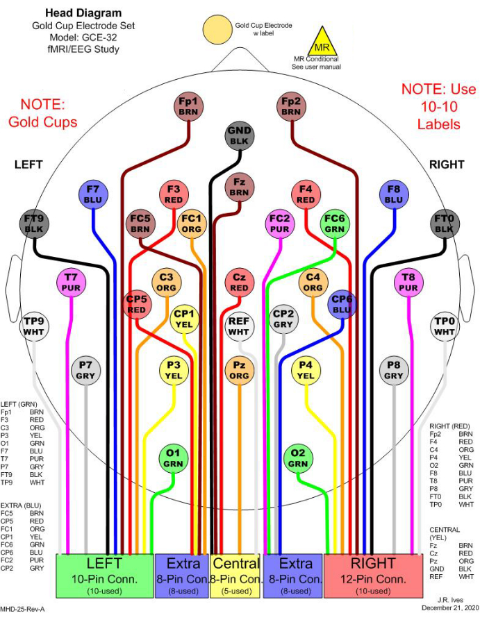
Figure 1: An example of 32 electrode selections for simultaneous EEG-fMRI recording. In the clinic, 21 channels are commonly considered for EEG monitoring. To fulfill a minimum number of electrodes to conduct EEG source imaging (ESI), 11 additional channels are included to cover the head entirely. All electrodes are gold cups to avoid MR effects. In the figure, different colors are used to distinguish different electrodes, and the colors match the physical cable colors. Each rectangular box in the bottom indicates one junction to be connected to a harness, which will be connected to an amplifier for recording. Please click here to view a larger version of this figure.
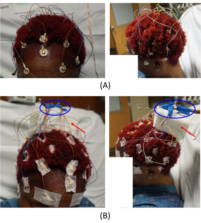
Figure 2: Electrode placements. (A) Placement of the electrodes on the patient's scalp and (B) arrangement of the cable junctions. The left images in (A) and (B) provide a top-front view, and the right images provide a left-side view of the patient. The red arrows in (B) indicate the placement of gauze pads. This helps to avoid imaging artifacts. The areas circled in blue in (B) show how the cable junctions are arranged. Please click here to view a larger version of this figure.
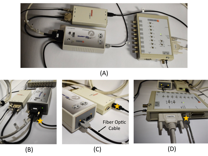
Figure 3: Equipment connection in the monitoring room. (A) An overview of the USB 2 adapter, Syncbox, and Triggerbox connection. Detailed picture of (B) the USB 2 adapter and Syncbox cable connections, (C) the Syncbox and the fiber optic cable connection, and (D) the cable connections in the Triggerbox. The star marks on (B), (C), and (D) show the location of the USB cables to be connected to the recording PC. A schematic diagram of the EEG recording system and the connections required between the hardware is provided in Figure 1 in Mullinger et al.7. Please click here to view a larger version of this figure.
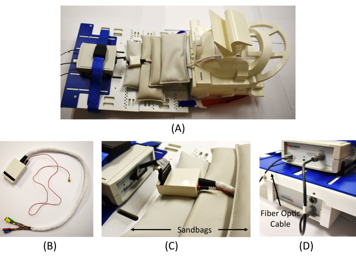
Figure 4: Equipment connection in the scanning room. (A) An overview of the EEG amplifier connection in the scanner. (B) Wrapped cables from the interface box to connect the EEG electrodes (the red cable is for the ECG measure). (C) Connection of the interface box and the EEG amplifier and MR safe sandbags placed to reduce MR artifacts. (D) Connection of the amplifier (top) and the battery (bottom) and connection of the fiber optic cable from the Syncbox in the monitoring room to the amplifier. Please click here to view a larger version of this figure.
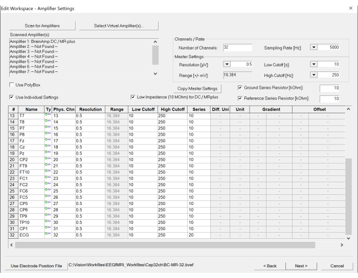
Figure 5: Screenshot of workspace settings on the EEG recording software. The number of channels and sampling rate can be set under the amplifier settings. In addition, the specification of each channel can be modified, if necessary, by clicking the table at the bottom. Please click here to view a larger version of this figure.
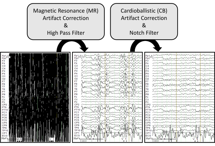
Figure 6: EEG artifact removal pipeline with representative examples. The raw EEG traces are displayed in the bottom left. The bottom middle plot shows EEG traces after applying MR artifact correction and a high pass filter of 0.5 Hz on the raw EEG. The bottom right plot displays EEG traces after applying CB artifact correction and a notch filter of 60 Hz on the processed EEG. The EEG traces are displayed under common ground mode to effectively visualize how each process influences each recorded channel. Please click here to view a larger version of this figure.
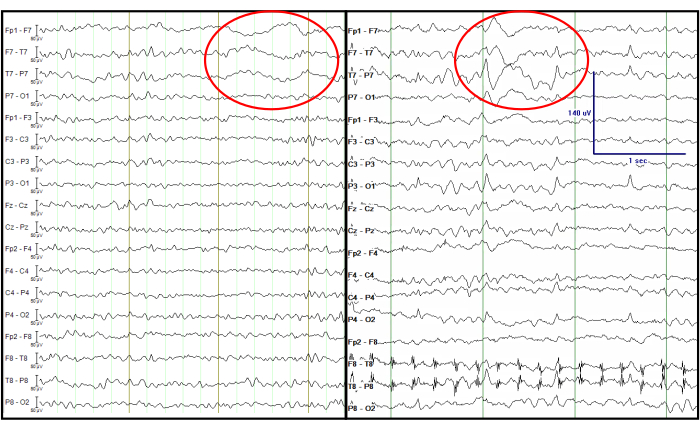
Figure 7: Comparison of the processed EEG from a simultaneous EEG-fMRI recording (left) and an EEG recorded at the EMU (right). The red circle indicates focal left temporal slow waves at the same channels. The EEG traces are displayed in a double banana format, which is traditionally considered in the clinic. Please click here to view a larger version of this figure.
Discussion
This experimental protocol is unique in providing a smooth transition of patients with epilepsy from the EMU to the scanning room, allowing it to be used in clinical and research settings. The use of FDA-approved MR conditional electrodes is an essential component for both clinical recordings during the time spent in the EMU and for safe transfer to MRI without having to remove or exchange the scalp electrodes from the patient. In the EMU, the MR conditional electrodes are connected to an amplifier for simultaneous video and EEG monitoring. For EEG-fMRI recordings, an MR conditional EEG amplifier and an MRI scanner can be used with a 20-channel head-coil, which accommodates the size of the electrode set and connecting wires. It must be noted that before conducting the simultaneous EEG-fMRI recordings in patients with epilepsy, a test run with a healthy subject is highly recommended to confirm the proper operation of all equipment and to become familiar with each required step.
In addition, concrete organization of the team and careful selection of patients also play a significant role in this protocol. To be viable for both clinical and research settings, it is required to have a structured team of epileptologists, nursing staff, EEG technologists, and engineers. For patient selection, the above-listed inclusion and exclusion criteria must be firmly considered.
Furthermore, it is important to address that when EEG-informed fMRI analysis is conducted, clear presence of the key features of EEGs must exist to guide the corresponding BOLD changes in fMRI. Therefore, when conducting the EEG-fMRI recording, it is important to consider patients who have previously demonstrated target EEG features. During the interictal period in patients with epilepsy, IEDs, which are abnormal and suggest epileptogenic potential, are a well-known EEG feature to reference to the BOLD changes16, even though the example here does not include this case. When targeting to obtain IEDs in the interictal EEG-fMRI recordings, experimenters should consider patients with frequent IEDs (at least three IEDs/hour) observed by a scalp EEG, in order to ensure sufficient epileptiform discharges during a scanning session. The number of IEDs can be determined from the EEG monitoring in the EMU, or from referencing the IED frequency seen in the subjects' prior EEG recordings if they exist. The obtained recordings of interictal EEG-fMRI data can bring benefits to understanding and potentially localizing the seizure onset zone17.
Once a clean EEG is obtained after processing the artifact removal steps, further EEG analysis can be applied. For example, EEG source imaging (ESI) can be obtained by applying standardized low-resolution brain electromagnetic tomography (sLORETA)18 to estimate the brain's corresponding electrical activity on the cortical surface. The estimated sources can be obtained by inverting the computed lead field matrix based on the head, outer skull, inner skull, and cortex layers created from the patient's MRI using the boundary element method19. There are numerous publicly available toolboxes to obtain EEG source imaging, and Brainstorm is one popularly used MATLAB-based toolbox20.
When ESI is considered using the processed EEG, the total number of electrodes and their distributions must be carefully taken into account so that they can reasonably cover the entire head. The minimum number of electrodes necessary to implement ESI is 32 channels21,22, which is more than the standard number of electrodes used in clinical settings. Thus, it is recommended to include extra channels to cover the entire head with reasonable spacing. The channel selection in this study includes 21 channels, which are conventionally used in the clinic for EEG monitoring, and 11 additional channels to cover the head entirely (Figure 1).
Here, we do not include details of fMRI analysis, since this is out of the scope of our study. However, a possible direction is EEG-informed fMRI analysis23. For instance, the occurrence time of IEDs can be saved as event triggers to correlate with the fMRI, which can lead to a routine event-related fMRI analysis. In this case, a generalized linear model analysis can be used to find the brain regions showing changes in fMRI signal at the time of IEDs.
We point out that a recently published study10 has shown it is possible to use a carbon wire loop system when a more robust artifact removal technique is required16. However, we want to apprise that the integration of the carbon wire loop system in our experimental setting with the MR conditional electrode has not been investigated yet.
Even though this study specifically focuses on the interictal period of epilepsy, the introduced protocol for simultaneous EEG-fMRI can be further extended to the ictal or postictal period. However, specific considerations must be followed when any customized settings are considered. For the postictal phase, an important concern that we are cognizant of is that the patient is given a benzodiazepine prior to transport to the MRI. As for the frequency analysis of EEGs, it has been reported that benzodiazepines do not necessarily alter the specific frequency bands24,25, and in the case of modest changes, these are confined to the somatosensory-motor region26 or frontal lobes27. Furthermore, with respect to simultaneous EEG-fMRI, delta EEG-BOLD correlations showed no changes after benzodiazepine injection compared to a control with saline injection27. The BOLD signal was decreased in only the small areas of Heschel's gyrus and supplementary motor area.
Disclosures
The authors have nothing to disclose.
Acknowledgements
This work was partially supported by the College of Medicine, the Vice President for Research, UK HealthCare, and the Research Priority Area at the University of Kentucky as part of the College of Medicine Alliance Initiative and Dr. Jihye Bae's Start-Up funds provided by the Department of Electrical and Computer Engineering at the University of Kentucky. The authors thank the volunteer participants for the recording and the Epilepsy-Neuroimaging Research Alliance team members, especially Dr. Brian Gold for leading the alliance team, Dr. Sridhar Sunderam for research mentorship, and Susan V. Hollar and Emily Ashcraft for patient care and management.
Materials
| 3T Magnetom Prisma fit MRI scanner | Siemens Healthineers | ||
| Abralyt HiCl, 10 g. | EASYCAP GmbH | Conductive gel for ECG electrode. | |
| BrainAmp MR plus 32-channel | Brain Products GmbH | S-BP-01300 | |
| BrainVision Analyzer Version 2.2.0.7383 | Brain Products GmbH | EEG analysis software. | |
| BrainVision Interface Box 32 inputs | Ives EEG Solutions, LLC | BVI-32 | |
| BrainVision Recorder License with dongle | Brain Products GmbH | S-BP-170-3000 | |
| BrainVision Recorder Version 1.23.0003 | Brain Products GmbH | EEG recording software. | |
| Collodion (non-flexible) | Mavidon | Glue to secure EEG electrodes. | |
| Fiber Optic cable (30m one line) | Brain Products GmbH | S-BP-345-3020 | |
| Gold Cup Electrode set, 32 channel | Ives EEG Solutions, LLC | GCE-32 | 2+ items are recommended when managing multiple subjects with overlapped/close period of Epilepsy Monitoring Unit (EMU) stay. |
| Gold Cup Electrodes | Ives EEG Solutions, LLC | GCE-EKG | |
| Harness, 32 lead, reusable | Ives EEG Solutions, LLC | HAR-32 | 2+ items are recommended when managing multiple subjects with overlapped/close period of Epilepsy Monitoring Unit (EMU) stay. |
| MR-sled kit including 100% and 75% length base plates, low profile (3 cm) block legs for each base plate, ramp, and strap systems as hand configured | Brain Products GmbH | BV-79123-PRISMA SKYRA | |
| Natus NeuroWorks EEG | Natus | Software used for EEG monitoring at the Epilepsy Monitoring Unit (EMU). | |
| Nuprep Skin Prep Gel | Weaver and Co. | ||
| Passive starter set, including consumables (gel, syringes, dispensing tips, adhesive washers, etc.) to facilitate out of the box data acquisition | Brain Products GmbH | S-C-5303 | |
| SyncBox compl. Extension box for phase sync recordings | Brain Products GmbH | S-BP-02675 | Syncbox |
| syngo MR XA30 | Siemens Healthineers | Software used for the MRI scanner. | |
| Ten 20 Conductive Neurodiagnostic Electrode Paste | Weaver and Co. | Conductive gel for EEG electrodes. | |
| TriggerBox Kit for BrainAmp | Brain Products GmbH | S-BP-110-9010 | Triggerbox; This Kit allows to expand the trigger width from the scanner so that the trigger signal can be detected on the BrainVision Recorder properly. This kit may not be required depending on the characteristics of the trigger signal provided by the scanner. |
| Xltek EMU40EX amplifier | Natus | An amplifier used at the Epilepsy Monitoring Unit (EMU). |
References
- Ngugi, A. K., Bottomley, C., Kleinschmidt, I., Sander, J. W., Newton, C. R. Estimation of the burden of active and life-time epilepsy: a meta-analytic approach. Epilepsia. 51 (5), 883-890 (2010).
- Kwan, P., Brodie, M. J. Early Identification of refractory epilepsy. The New England Journal of Medicine. 342 (5), 314-319 (2000).
- Menon, V., Crottaz-Herbette, S. Combined EEG and fMRI studies of human brain function. International Review of Neurobiology. 66, 291-321 (2005).
- Gotman, J., Pittau, F. Combining EEG and fMRI in the study of epileptic discharges. Epilepsia. 52, 38-42 (2011).
- Pittau, F., Dubeau, F., Gotman, J. Contribution of EEG/fMRI to the definition of the epileptic focus. Neurology. 78 (19), 1479-1487 (2012).
- Ikemoto, S., von Ellenrieder, N., Gotman, J. Electroencephalography-functional magnetic resonance imaging of epileptiform discharges: Noninvasive investigation of the whole brain. Epilepsia. 63 (11), 2725-2744 (2022).
- Mullinger, K. J., Castellone, P., Bowtell, R. Best current practice for obtaining high quality EEG data during simultaneous fMRI. Journal of Visualized Experiments. (76), e50283 (2013).
- Douglas, P. K., et al. Method for simultaneous fMRI/EEG data collection during a focused attention suggestion for differential thermal sensation. Journal of Visualized Experiments. (83), e3298 (2014).
- Nguyen, T., Potter, T., Karmonik, C., Grossman, R., Zhang, Y. Concurrent EEG and functional MRI recording and integration analysis for dynamic cortical activity imaging. Journal of Visualized Experiments. (136), e56417 (2018).
- Khoo, H. M., et al. Reliable acquisition of electroencephalography data during simultaneous electroencephalography and functional MRI. Journal of Visualized Experiments. (169), e62247 (2021).
- Allen, P. J., Josephs, O., Turner, R. A method for removing imaging artifact from continuous EEG recorded during functional MRI. Neuroimage. 12 (2), 230-239 (2000).
- Smith, S. J. M. EEG in the diagnosis, classification, and management of patients with epilepsy. Journal of Neurology, Neurosurgery, and Psychiatry. 76, 2-7 (2005).
- Manganotti, P., et al. Continuous EEG-fMRI in patients with partial epilepsy and focal interictal slow-wave discharges on EEG. Magnetic Resonance Imaging. 26 (8), 1089-1100 (2008).
- Reiher, J., Beaudry, M., Leduc, C. P. Temporal intermittent rhythmic delta activity (TIRDA) in the diagnosis of complex partial epilepsy: sensitivity, specificity and predictive value. The Canadian Journal of Neurological Sciences. 16 (4), 398-401 (1989).
- Geyer, J. D., Bilir, E., Faught, R. E., Kuzniecky, R., Gilliam, F. Significance of interictal temporal lobe delta activity for localization of the primary epileptogenic region. Neurology. 52 (1), 202-205 (1999).
- Koupparis, A., et al. Association of EEG-fMRI responses and outcome after epilepsy surgery. Neurology. 97 (15), e1523-1536 (2021).
- Gotman, J. Has recording of seizures become obsolete. Revue Neurologique. , 00865 (2023).
- Pascual-Marqui, R. D. Standardized low-resolution brain electromagnetic tomography (sLORETA): technical details. Methods and Findings in Experimental and Clinical Pharmacology. 24, 5-12 (2002).
- Hallez, H., et al. Review on solving the forward problem in EEG source analysis. Journal of Neuroengineering and Rehabilitation. 4, 46 (2007).
- Tadel, F., Baillet, S., Mosher, J. C., Pantazis, D., Leahy, R. M. Brainstorm: a user-friendly application for MEG/EEG analysis. Computational Intelligence and Neuroscience. 2011, 879716 (2011).
- Srinivasan, R., Tucker, D. M., Murias, M. Estimating the spatial Nyquist of the human EEG. Behavior Research Methods, Instruments, & Computers. 30, 8-19 (1998).
- Michel, C. M., et al. EEG source imaging. Clinical Neurophysiology. 115 (10), 2195-2222 (2004).
- Abreu, R., Leal, A., Figueiredo, P. EEG-informed fMRI: A review of data analysis methods. Frontiers in Human Neuroscience. 12, 29 (2018).
- Saletu, B., Anderer, P., Saletu-Zyhlarz, G. M. EEG topography and tomography (LORETA) in the classification and evaluation of the pharmacodynamics of psychotropic drugs. Clinical EEG Neuroscience. 37 (2), 66-80 (2006).
- Windmann, V., et al. Influence of midazolam premedication on intraoperative EEG signatures in elderly patients. Clinical Neurophysiology. 130 (9), 1673-1681 (2019).
- Nishida, M., Zestos, M. M., Asano, E. Spatial-temporal patterns of electrocorticographic spectral changes during midazolam sedation. Clinical Neurophysiology. 127 (2), 1223-1232 (2016).
- Forsyth, A., et al. Comparison of local spectral modulation, and temporal correlation, of simultaneously recorded EEG/fMRI signals during ketamine and midazolam sedation. Psychopharmacology. 235 (12), 3479-3493 (2018).

