Microfluidic-based Synthesis of Covalent Organic Frameworks (COFs): A Tool for Continuous Production of COF Fibers and Direct Printing on a Surface
Summary
We present a novel microfluidic-based method for synthesis of covalent organic frameworks (COFs). We demonstrate how this approach can be used to produce continuous COF fibers, and also 2D or 3D COF structures on surfaces.
Abstract
Covalent Organic Frameworks (COFs) are a class of porous covalent materials which are frequently synthesized as unprocessable crystalline powders. The first COF was reported in 2005 with much effort centered on the establishment of new synthetic routes for its preparation. To date, most available synthetic methods for COF synthesis are based on bulk mixing under solvothermal conditions. Therefore, there is increasing interest in developing systematic protocols for COF synthesis that provide for fine control over reaction conditions and improve COF processability on surfaces, which is essential for their use in practical applications. Herein, we present a novel microfluidic-based method for COF synthesis where the reaction between two constituent building blocks, 1,3,5-benzenetricarbaldehyde (BTCA) and 1,3,5-tris(4-aminophenyl)benzene (TAPB), takes place under controlled diffusion conditions and at room temperature. Using such an approach yields sponge-like, crystalline fibers of a COF material, hereafter called MF-COF. The mechanical properties of MF-COF and the dynamic nature of the approach allow the continuous production of MF-COF fibers and their direct printing onto surfaces. The general method opens new potential applications requiring advanced printing of 2D or 3D COF structures on flexible or rigid surfaces.
Introduction
Covalent organic frameworks (COFs) are a well-established class of porous and crystalline material in which the organic building blocks are firmly held together by covalent bonds1,2,3,4,5. COFs are typically assembled following supramolecular chemistry principles, where the constituent molecular building blocks are selectively reacted to define a final and predetermined porous assembly. Such an approach allows the synthesis of materials with controlled and ordered structure (e.g.,with defined pore dimensions) and composition3,6,7,8. Compared to other porous materials, COFs are unique since they are comprised of light elements (C, H, B, N and O) and have tunable porosities1,5. Inspired by these unique and intrinsic characteristics, COFs have been assessed for potential application in chemical separations9, gas storage10and catalysis11, sensors12, optoelectronics13, clean energy technologies14 and electrochemical energy devices15.
To date, the vast majority of methods used for the preparation of COF materials are based on solvothermal self-condensation and co-condensation reactions, where high temperatures and pressures are the standard. Although COFs are thermally robust, they commonly suffer from limited processability, i.e., COFs are usually insoluble and unprocessable crystalline powders, and this significantly limits their use in a range of potential and practical applications2,6,8,16,17. Despite the remarkable progress made in COF synthesis, a major challenge in the field is to develop a method enabling the preparation of COFs in appropriate reaction conditions (e.g., temperature and pressure), which can then facilitate their processability on surfaces.
Recently, studies have shown that Shiff-base chemistry can be used to synthesize an imine-based COF at room temperature. The COF produced, named RT-COF-1, forms due to the fast and efficient reaction between 1,3,5-tris(4-aminophenyl)benzene (TAPB) and 1,3,5-benzenetricarbaldehyde (BTCA)17 (Figure 1A). The efficacy of this synthetic method was demonstrated by the direct printing of micron and submicron patterns of RT-COF-1 on both rigid and flexible surfaces using lithography or inkjet printing techniques. More recently, and making use of microfluidics, we have demonstrated an effective approach for the continuous synthesis of fibers of the same imine-based COF hereafter called MF-COF6. Unlike other reported synthetic approaches for the generation of COFs18, this microfluidic-based synthetic method enabled the rapid synthesis of MF-COF fibers at ambient temperatures and pressures within a few seconds. Furthermore, and owing to the mechanical stability of the synthesized MF-COF fibers, we have demonstrated how such microfluidic-based method can enable the direct printing of 2D and 3D structures on surfaces. Herein, we demonstrate that this method can be used to draw COF structures on various surfaces having different chemical and physical properties. We believe that this novel method opens new avenues for the well-controlled patterning and direct printing of COFs in different orientations and on various surfaces.
Protocol
1. Master Mold Fabrication
- Perform the photolithographic fabrication of a 4 inch silicon master mold as described in detail previously19; the master mold used in this study has been fabricated using the same protocol.
NOTE: Microfluidic devices are typically fabricated through a multi-step process. The first step is the design of the microfluidic channel using a conventional drawing software. Then, high-resolution film photomasks containing the microfluidic network are produced with a feature precision of approximately 5 µm. Next, master molds are fabricated on a 4-in silicon wafer through standard photolithography techniques. SU-8, a negative photoresist, is employed for the fabrication of the master molds in the current investigations. The height of SU-8 structures is defined to be 50 µm in our devices. Finally, microfluidic devices are fabricated by directly casting a transparent polymer, normally polydimethylsiloxane (PDMS), against the master mold.
2. Fabrication of Single-layer Microfluidic Devices
NOTE: The protocol requires an oven operating at 70 °C. The temperature of the oven should be stabilized at 70 °C before initiating the fabrication protocol. Lower temperatures can lead to poorly bonded and non-functional devices.
- Place the fabricated master mold in a desiccator, equipped with a vacuum pump. Then, pour 100 µL of chlorotrimethylsilane in a glass vial and place this inside the desiccator.
NOTE: CAUTION! Chlorotrimethylsilane is a corrosive, hazardous and toxic substance. Accordingly, all handling steps should be performed under a well-ventilated fume hood, and appropriate protective goggles, gloves and lab coat must be worn. - Close the desiccator and put under vacuum (in this experiment, 51 mbar). Wait for at least 1 h to ensure the deposition of vaporized chlorotrimethylsilane on the surface of master mold. After 1 h, gently open the air valve of the desiccator to equilibrate it to atmospheric pressure and open it.
NOTE: CAUTION! As soon as the desiccator is opened, chlorotrimethylsilane vapor leaks out; do not breath directly above the desiccator and always perform the above in a ventilated fume hood. - Carefully take out the silanized master mold by hand and close the desiccator. Store the master mold in a closed box (or inside a laminar flow hood) to avoid deposition of particulates on its surface.
NOTE: All proceeding steps must be performed under a laminar flow hood operating with a uniform air velocity. - Prepare a mixture of PDMS pre-polymer and curing agent (10:0.9 in weight) in a disposable cup and mix vigorously with a plastic spatula. As a guide, use 20 g of elastomer and 1.8 g curing agent to fabricate four PDMS microfluidic devices approximately 5 mm thick.
- Place the cup containing the well-mixed PDMS in a desiccator under vacuum to degas and remove air bubbles. Once the PDMS is degassed, open the desiccator and remove the cup.
NOTE: In this experiment, it takes approximately 30 min at 51 mbar. - Gently place four square frames (e.g., polytetrafluoroethylene (PTFE) frames with inner dimensions of 24 mm x 24 mm) on the master mold such that each forms a wall around a single patterned structure on the master mold.
- Pour the degassed PDMS into the frames and on top of the master mold until full. Place the master mold with the filled square frames in an oven at 70 °C for 2 h.
- After 2 h, remove the master mold from the oven and leave the assembly to cool to room temperature.
- Manually peel off the structured PDMS slabs (or PDMS chips) and the square frames by carefully separating them from the master mold and slide the PDMS chips out of the square frames.
- Punch inlet and outlet holes using a 1.5 mm biopsy puncher at desired positions in the design, e.g., at the end of the microfluidic channels. Cut the extra pieces of PDMS and remove any debris from the surface of the structured PDMS chips using adhesive tape.
- Place the PDMS chips (with the open channels facing up) as well as the glass coverslips, into the chamber of a plasma generator and close the chamber.
- Put the plasma generator under vacuum (1.4 mbar here); switch the plasma generator on for 1 min.
- After 1 min, switch the plasma generator off, ventilate the chamber and take out the treated PDMS chips and glass coverslips. Bond the PDMS chips (from the side with structured channels) and glass coverslips together to close the channels; at this point the single-layer microfluidic devices are fabricated.
- Finally, place the bonded microfluidic devices in an oven at 70 °C for at least 4 h to enhance the bonding between the PDMS and glass, substantially.
3. Preparation of the Microfluidic Set-up and Precursor Solutions
- Prepare a 0.040 M solution of BTCA in acetic acid.
NOTE: CAUTION! Acetic acid is a hazardous, corrosive and flammable compound and its vapor is extremely irritating to the eyes and respiratory system. Accordingly, handling steps must be performed in a fume hood. Also, the user must wear a protective lab coat, goggles and gloves. - Prepare a 0.040 M solution of TAPB in acetic acid.
NOTE: The microfluidic device used in the current experiments has four inlet channels (Figure 1B and Figure 2). - Load BTCA and TAPB solutions into two different syringes (5 mL syringes loaded with 3 mL solution here), place and secure the syringes onto a syringe pump and connect them to the two middle inlets of the fabricated microfluidic chip (one reagent per inlet) using PTFE tubing (0.8 mm inner diameter).
- Load two other syringes with pure acetic acid (here 5 mL syringes fully loaded), place and secure the syringes onto the syringe pump and connect them to the two side inlets of the microfluidic chip using the same type of PTFE tubing.
- Connect a sufficiently long PTFE tubing (in the current experiment, ~15 cm) to the outlet of the microfluidic chip. Use a computer-controlled syringe pump to motivate fluid flows as described in the following steps.
4. Continuous Synthesis of MF-COF Fibers
- Using the syringe pump introduce two sheath flows of acetic acid each at a flow rate of 100 µL/min; the sheath flows are located on the outer side of the reagent flows (Figure 2).
- Wait for 1 min and inject the two reagents (TAPB and BTCA) via the two middle inlets (one reagent per inlet) each at a flow rate of 50 µL/min. Wait for 1 min until stable flows are established.
- Observe the formation of yellow fibrous microstructures previously characterized as MF-COF by Fourier transform infrared (FT-IR) spectroscopy, elemental analysis and solid state 13C CP-MAS-NMR6; under these conditions the formation of MF-COF is not continuous.
- Increase the flow rate of TAPB and BTCA to 200 µL/min and maintain the two sheath flows of acetic acid at 100 µL/min. Now wait for 1 min until the flow stabilizes. Observe the formation of a highly-concentrated suspension of yellow MF-COF fibers, which ultimately leads to blockage of the outlet.
- As the chip and outlet tubing are now non-functional, use a new chip and prepare it for experiment according to steps 3.3-3.6.
- Introduce two sheath flows of acetic acid each at a flow rate of 100 µL/min and wait for 1 min. Set the flows of TAPB and BTCA each to 100 µL/min and observe the formation of a continuous yellow MF-COF fiber.
- Place the outlet of the tubing in a Petri dish containing acetic acid. For example, place 10 mL of acetic acid in a round glass Petri dish (60 mm in diameter). Once the synthesized fiber exits the tube located at the outlet of the microfluidic device, move the tube over a surface to facilitate the exit of the continuous MF-COF fiber.
5. Direct Printing of 2D and 3D MF-COF Structures
NOTE: As the synthetized fiber may not be completely homogeneous, the deposition speed must be adjusted to ensure continuous printing.
- Prepare the microfluidic set-up as described in section 3 and inject all four solutions each at a flow rate of 100 µL/min.
- Wait for 1 min until the flows are stabilized and the synthesized MF-COF fiber exits the tube located at the outlet of the microfluidic device. Prepare a clean substrate next to the exit of the tube located at the outlet of the microfluidic device for direct printing of MF-COF fibers.
NOTE: In our investigations, 24 mm x 76 mm glass coverslips were employed for all printing experiments. - Hold the tube connected to the outlet of the microfluidic device so that its end is a few millimeters above the glass coverslip. Slowly move the tube over the glass coverslip to facilitate the exit of the MF-COF fiber and avoid aggregation.
- Once the flows are stabilized, slowly lift the tube located at the outlet of the microfluidic device approximately 2-3 cm away from the glass coverslip to observe a freestanding and stable MF-COF fiber.
- To continue printing, bring the outlet of the tube back towards the glass coverslip and manually move the tube on the surface to draw the desired 2D or 3D MF-COF structure.
Representative Results
The microfluidic device used in our investigations is fabricated using conventional PDMS replica molding20 and incorporates four microfluidic inlet channels that merge into a main microchannel. The final microfluidic device consists of a structured PDMS layer and a glass coverslip used to close the imprinted microchannels, as shown in Figure 1B.
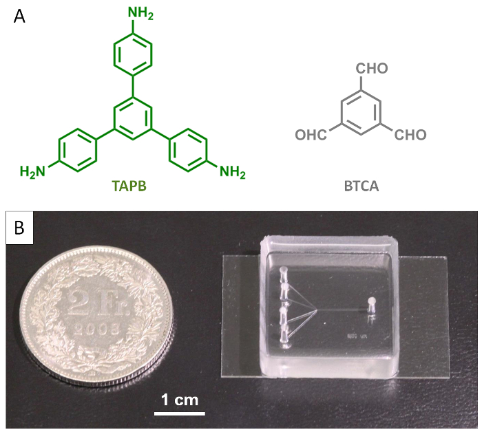
Figure 1: Molecular building blocks and the single-layer microfluidic device. (A) Chemical structures of TAPB and BTCA. (B) Photograph of the microfluidic device used for synthesis of COF fibers. Please click here to view a larger version of this figure.
The four inlet microfluidic channels are 50 µm high and 50 µm wide and converge into a main microfluidic channel 50 µm high and 250 µm wide. The two reagent flows (BTCA and TAPB both in acetic acid) are injected into the two middle input channels, while two sheath flows of pure acetic acid are introduced into the side channels (Figure 2, synthesis zone). All the four flows converge in the main microfluidic channel, where the reaction takes place under diffusion control. In this work, all four input flows are adjusted to a flow rate of 100 µL/min. This condition, on one hand, ensures the formation of a continuous MF-COF fiber (with the production rate of ca. 2 mg/min of dried MF-COF fibers), and on the other, avoids blockage of both the main microfluidic channel as well as the tube located at the outlet of the microfluidic device. Such optimized flow conditions allow for the production of a continuous yellow MF-COF fiber with suitable mechanical properties for direct printing on surfaces (Figure 2, Printing zone).
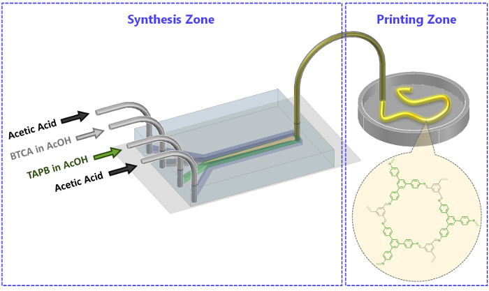
Figure 2: Schematic illustration of the microfluidic set-up used for the synthesis of MF-COF fibers. The synthesis and printing zones are indicated. Please click here to view a larger version of this figure.
Our previous study6 provides detailed chemical characterization studies as well as thermal stability analysis of the synthetized MF-COF fibers. Figure 3 shows the attenuated total reflectance FT-IR (ATR-FT-IR) data and powder X-Ray diffraction (PXRD) patterns of monomers TAPB and BTCA as well as MF-COF fibers. The ATR-FT-IR measurements indicate the disappearance of N-H stretching bands (3,300-3,500 cm-1) in the MF-COF fibers and the appearance of a new band located at 1,689 cm-1, which corresponds to the imine bond formation. Moreover, the PXRD data of MF-COF fibers compare well to the simulated pattern. Interestingly, the morphological characterization of MF-COF revealed that MF-COF differ from RT-COF-1 (synthetized under bulk conditions) in that MF-COF consists of interconnected micro- and nano-fibers forming 3D sponge-like porous organizations, while RT-COF-1 forms films containing no defined microstructures17. This morphology difference also explains a notable increase in N2 adsorption in MF-COF, as demonstrated by total specific surface areas determined by Brunauer-Emmet-Teller (BET) analyses6.
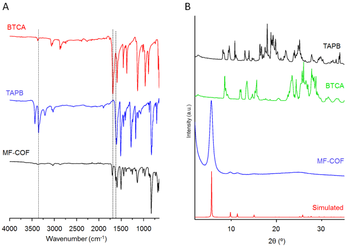
Figure 3: Chemical and structural analysis of reagents and MF-COF fibers. (A) ATR-FT-IR spectra of monomers TAPB and BTCA as well as MF-COF fibers. (B) PXRD patterns of MF-COF fibers (with a simulated pattern) and of TAPB and BTCA. Please click here to view a larger version of this figure.
These results demonstrate that COFs synthetized using microfluidic reactions are unique and that MF-COF characteristics and performance cannot be achieved using alternative synthetic approaches. The mechanical properties, derived from the microscopic organization of MF-COF, allow the conformal printing of MF-COF fibers on surfaces. Figure 4 illustrates different 2D and 3D MF-COF structures printed on glass surfaces using this microfluidic-based synthetic method.
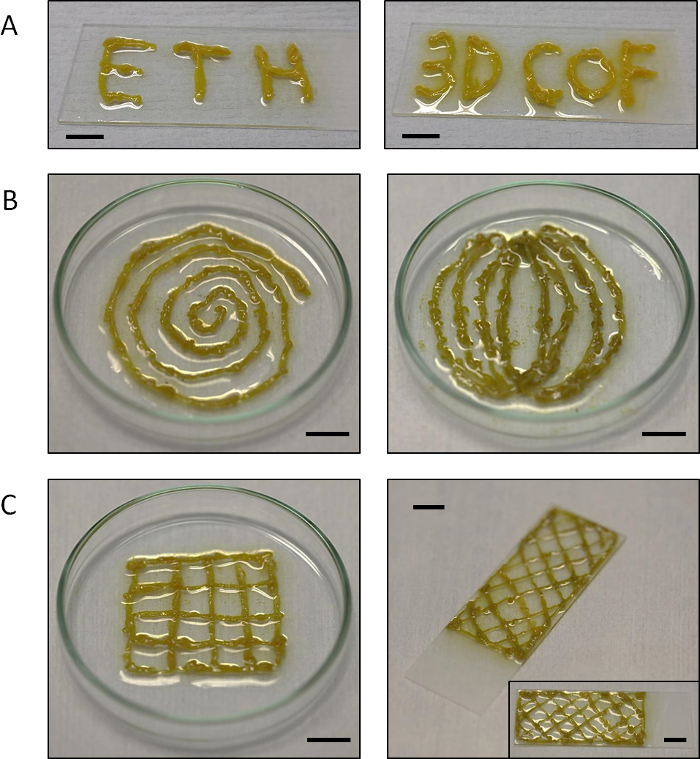
Figure 4: 2D and 3D MF-COF structures on glass surfaces. Photographs of (A) writing experiments (with the words "ETH" and "3D COF") as well as printing experiments of (B) two-dimensional and (C) three-dimensional MF-COF structures on glass. Scale bars =1 cm. Please click here to view a larger version of this figure.
Furthermore, the mechanical properties of the synthesized MF-COF fibers, together with the simplicity and flexibility of the printing approach, allow for the controlled deposition of MF-COF on different flexible and rigid substrates. As illustrated in Figure 5, MF-COF can be printed onto various surfaces such as glass, tissue paper, cardboard, aluminum foil and polystyrene.
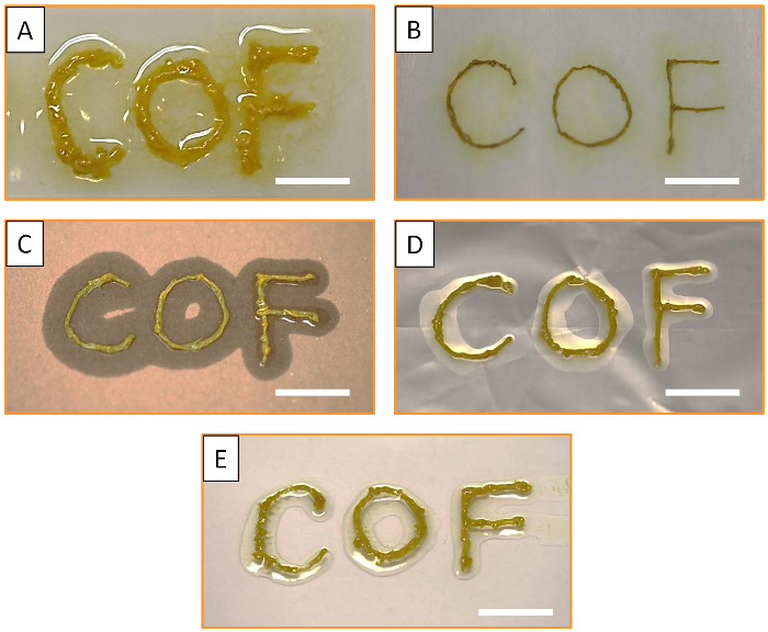
Figure 5: Printing of MF-COF fibers on different substrates. Photographs of MF-COF printed on (A) glass, (B) tissue paper, (C) cardboard, (D) aluminum foil and (E) polystyrene surfaces. All scale bars are 1 cm. Please click here to view a larger version of this figure.
Discussion
The microfluidic-based synthetic method reported here provides a novel and simple approach for direct printing of COF materials on surfaces. Synthesis is performed using a single-layer microfluidic device, comprised of a microfluidic PDMS chip bonded to a glass coverslip. The fabrication of the microfluidic device can be achieved through conventional casting of PDMS against a silicon master mold and subsequently bonding the PDMS with the imprinted microchannels against a glass coverslip.
For the successful assembly of the microfluidic device, it is important to fabricate the master mold in a cleanroom environment to avoid contamination and defects during photolithography. As a consequence of unsuitable conditions, defective master molds will lead to non-functional microfluidic devices. Additionally, the ratio of PDMS pre-polymer to curing agent, which controls the stiffness of the PDMS, has been optimized to fabricate robust PDMS devices that still have sufficient elasticity. The elasticity of the PDMS chip is important in facilitating the stable insertion of PTFE tubing into the inlet and outlet holes of the microfluidic device.
The laminar flow conditions present in microfluidic devices allow for a fine control over the chemical reactions taking place at the interface between co-flowing reagent streams. The advanced mixing of regents facilitated inside microfluidic devices actively contributes to the formation and isolation of micro- and nanostructures that are not accessible through other synthetic methods6,21,22,23. In the present study, we also show that microfluidic synthesis can lead to the formation of 3D sponge-like COF materials with interconnected fibrous microstructures, different to those obtained by conventional bulk synthetic methods.
The chemical and physical characterization of MF-COF fibers demonstrates that the material produced agrees with the expected COF obtained from bulk synthetic approaches6. However, the microfluidic synthesis facilitates the formation of a macroscopic and porous MF-COF fiber that can be continuously printed on different surfaces. This novel method for synthesis and direct printing creates new opportunities in COF research.
Disclosures
The authors have nothing to disclose.
Acknowledgements
The authors acknowledge the Swiss National Science Foundation (SNF) for financial support through project no. 200021_160174.
Materials
| High resolution film masks | Microlitho, UK | – | Features down to 5um |
| Silicon wafers | Silicon Materials Inc., Germany | 4" Silicon Wafers | Front surface: polished, back surface: etched |
| Silicone Elastomer KIT (PDMS) | Dow Corning, USA | Sylgard 184 | – |
| Chlorotrimethylsilane | Sigma-Aldrich, Switzerland | 386529 | ≥97%, CAUTION: Handle it only under fume hood. |
| Biopsy puncher | Miltex GmBH, Germany | 33-31A-P/25 | 1.5 mm |
| Glass coverslip | Menzel-Glaser, Germany | BB024040SC | 24 mm × 40 mm, #5 |
| Plasma generator instrument | Diener | Zepto B | Frequency: 40 kHz and plasma generator power: 0-30 W |
| PTFE tubing | PKM SA, Switzerland | AWG-TFS-XXX | AWG 20TFS, roll of 100 m |
| neMESYS Syringe Pumps | Cetoni GmbH, Germany | Low Pressure (290N) | – |
| Disposable Cup | Semadeni, Switzerland | 8323 | PS, 200 ml |
| Plastic Spatula | Semadeni, Switzerland | 3340 | L × W : 135 mm x 14 mm |
| Disposable Scalpels | B. Braun, Switzerland | 233-5320 | Nr. 20 |
| Disposable Syringes | VWR, Switzerland | 613-3951 | 5 ml, Discardit II |
| Acetic Acid | Sigma-Aldrich, Switzerland | 695092-500 | >=99.7%, CAUTION: Handle it only under fume hood. |
| 1,3,5-benzenetricarbaldehyde | Aldrich-Fine Chemicals | 753491 | 97% |
| 1,3,5-Tris(4-aminophenyl)benzene | Tokyo Chemical Industry | T2728-5G | >93.0% |
References
- Cote, A. P., et al. Porous, crystalline, covalent organic frameworks. Science. 310, 1166-1170 (2005).
- Ding, S. Y., Wang, W. Covalent organic frameworks (COFs): from design to applications. Chem Soc Rev. 42, 548-568 (2013).
- Huang, N., Wang, P., Jiang, D. L. Covalent organic frameworks: a materials platform for structural and functional designs. Nat Rev Mater. 1, 16068 (2016).
- Xu, H., Gao, J., Stable Jiang, D. L. crystalline, porous, covalent organic frameworks as a platform for chiral organocatalysts. Nat Chem. 7, 905-912 (2015).
- Wan, S., Guo, J., Kim, J., Ihee, H., Jiang, D. L. A Belt-Shaped, Blue Luminescent, and Semiconducting Covalent Organic Framework. Angew Chem Int Edit. 47, 8826-8830 (2008).
- Rodriguez-San-Miguel, D., et al. Crystalline fibres of a covalent organic framework through bottom-up microfluidic synthesis. Chem Commun. 52, 9212-9215 (2016).
- Bisbey, R. P., DeBlase, C. R., Smith, B. J., Dichtel, W. R. Two-dimensional Covalent Organic Framework Thin Films Grown in Flow. J Am Chem Soc. 138, 11433-11436 (2016).
- Spitler, E. L., Dichtel, W. R. Lewis acid-catalysed formation of two-dimensional phthalocyanine covalent organic frameworks. Nat Chem. 2, 672-677 (2010).
- Keskin, S. Adsorption, Diffusion, and Separation of CH4/H-2 Mixtures in Covalent Organic Frameworks: Molecular Simulations and Theoretical Predictions. J Phys Chem C. 116, 1772-1779 (2012).
- Tilford, R. W., Mugavero, S. J., Pellechia, P. J., Lavigne, J. J. Tailoring microporosity in covalent organic frameworks. Adv Mater. 20, 2741-2746 (2008).
- Hasegawa, S., et al. Three-dimensional porous coordination polymer functionalized with amide groups based on tridentate ligand: Selective sorption and catalysis. J Am Chem Soc. 129, 2607-2614 (2007).
- Das, G., et al. Chemical sensing in two dimensional porous covalent organic nanosheets. Chem Sci. 6, 3931-3939 (2015).
- Guo, J., et al. Conjugated organic framework with three-dimensionally ordered stable structure and delocalized pi clouds. Nat Commun. 4, 2736 (2013).
- Furukawa, H., Yaghi, O. M. Storage of Hydrogen, Methane, and Carbon Dioxide in Highly Porous Covalent Organic Frameworks for Clean Energy Applications. J Am Chem Soc. 131, 8875-8883 (2009).
- Xu, F., et al. Electrochemically active, crystalline, mesoporous covalent organic frameworks on carbon nanotubes for synergistic lithium-ion battery energy storage. Sci Rep-Uk. 5, 8225 (2015).
- El-Kaderi, H. M., et al. Designed synthesis of 3D covalent organic frameworks. Science. 316, 268-272 (2007).
- Ruigomez, A. D., et al. Direct On-Surface Patterning of a Crystalline Laminar Covalent Organic Framework Synthesized at Room Temperature. Chem Eur J. 21, 10666-10670 (2015).
- Segura, J. L., Mancheno, M. J., Zamora, F. Covalent organic frameworks based on Schiff-base chemistry: synthesis, properties and potential applications. Chem Soc Rev. 45, 5635-5671 (2016).
- Abrishamkar, A., et al. Microfluidic Pneumatic Cages: A Novel Approach for In-chip Crystal Trapping, Manipulation and Controlled Chemical Treatment. J Vis Exp. (113), e54193 (2016).
- Duffy, D. C., McDonald, J. C., Schueller, O. J. A., Whitesides, G. M. Rapid prototyping of microfluidic systems in poly(dimethylsiloxane). Anal Chem. 70, 4974-4984 (1998).
- Rubio-Martinez, M., et al. Freezing the Nonclassical Crystal Growth of a Coordination Polymer Using Controlled Dynamic Gradients. Adv Mater. 28, 8150-8155 (2016).
- Liu, H., et al. A Catalytic Chiral Gel Microfluidic Reactor Assembled via Dynamic Covalent Chemistry. Chem Sci. 6, 2292-2296 (2015).
- Puigmarti-Luis, J., et al. Stepwise Template Growth of Functional Nanowires from an Amino Acid-Supported Framework in a Microfluidic Chip. ACS Nano. 8 (1), 818-826 (2014).

