Hyperpolarized Xenon for NMR and MRI Applications
Summary
The production of hyperpolarized xenon by means of spin exchange optical pumping (SEOP) is described. This method yields a ~10000-fold enhancement of the nuclear spin polarization of Xe-129 and has applications in nuclear magnetic resonance spectroscopy and imaging. Examples of gas phase and solution state experiments are given.
Abstract
Nuclear magnetic resonance (NMR) spectroscopy and imaging (MRI) suffer from intrinsic low sensitivity because even strong external magnetic fields of ~10 T generate only a small detectable net-magnetization of the sample at room temperature 1. Hence, most NMR and MRI applications rely on the detection of molecules at relative high concentration (e.g., water for imaging of biological tissue) or require excessive acquisition times. This limits our ability to exploit the very useful molecular specificity of NMR signals for many biochemical and medical applications. However, novel approaches have emerged in the past few years: Manipulation of the detected spin species prior to detection inside the NMR/MRI magnet can dramatically increase the magnetization and therefore allows detection of molecules at much lower concentration 2.
Here, we present a method for polarization of a xenon gas mixture (2-5% Xe, 10% N2, He balance) in a compact setup with a ca. 16000-fold signal enhancement. Modern line-narrowed diode lasers allow efficient polarization 7 and immediate use of gas mixture even if the noble gas is not separated from the other components. The SEOP apparatus is explained and determination of the achieved spin polarization is demonstrated for performance control of the method.
The hyperpolarized gas can be used for void space imaging, including gas flow imaging or diffusion studies at the interfaces with other materials 8,9. Moreover, the Xe NMR signal is extremely sensitive to its molecular environment 6. This enables the option to use it as an NMR/MRI contrast agent when dissolved in aqueous solution with functionalized molecular hosts that temporarily trap the gas 10,11. Direct detection and high-sensitivity indirect detection of such constructs is demonstrated in both spectroscopic and imaging mode.
Introduction
Hyperpolarized agents are gaining increasing attention for NMR/MRI applications since they can solve the sensitivity problem under certain circumstances 2. Three major approaches are currently used (dynamic nuclear polarization, DNP; para-hydrogen induced polarization, PHIP; and spin exchange optical pumping, SEOP) that all prepare an artificially increased spin population difference outside an NMR magnet prior to the actual spectroscopy or imaging experiment. Here we describe the function and operation of a SEOP setup that has been optimized for production of hyperpolarized129Xe used in solution state experiments.
An essential component is an intense light source emitting infrared photons at 795 nm. Laser diode arrays (LDA) are convenient devices that provide high power output > 100 W at reasonable cost. In many setups, the LDA is emitting into an optical fiber that more or less retains the polarization of the laser light. To guarantee a sufficient SEOP process this elliptical polarization must be converted into circular polarization of high purity. Major components of the polarization optics are shown in Figures 1 and 2 and setting up the system is explained schematically in supplementary movie 1.
To circularly polarize the light we first attach the fiber end to a primary beam expansion optics (e.g., a fiber collimator) for reducing power density. The light then passes through a polarizing beam splitter cube, generating linearly polarized light. By rotating this cube we can determine the preferred axis of the remaining polarization with a power meter. Maximum transmission corresponds to the situation where the fast axis of the cube is aligned with the principal light polarization axis. Cubes with high extinction coefficients (100,000 : 1 or better) yield a good separation of polarization components. This can be tested using a second beam splitter cube as an analyzer that is rotated while the first one is aligned for maximum transmission of the extra-ordinary beam.
Once the linear polarization of the transmitted light has been confirmed, a λ/4 wave plate designed for 795 nm is introduced into the extra-ordinary beam to convert linear into circular polarization. For this purpose, the fast axis of the wave plate is rotated by 45 ° relative to the beam splitter cube fast axis. (If desired, circular polarization of the reflected ordinary beam with its linear polarization axis perpendicular to the extra-ordinary beam can be achieved in a similar manner.)
The quality of the circular polarization can be tested with a second beam splitter cube that should yield constant transmission upon rotation. A secondary beam expansion optics (e.g. two lenses in a Galilean telescope configuration) then increases the beam diameter to completely illuminate the glass cell for the pumping process inside an oven box. Absorption of the laser light by Rb vapor in the cell is monitored through a pin hole behind the pumping cell at the end of the box: a collimator collects an attenuated IR beam to be analyzed with an optical spectrometer (see Figure 3 for pumping cell setup).
A heating mechanism outside the pumping cell partially vaporizes a Rb droplet sitting inside the cell (Figure 4a) and therefore causes laser light absorption. Density of the vapor can be adjusted via the heating set point of the respective PID controller. High temperatures (ca. 190 °C) are good for compact setups where the xenon has a limited amount of time to build up polarization. The gas mixture containing Xe, N2 and He flows through the pumping cell opposite to the laser beam direction (Figure 3). An external magnetic field aligned with the laser beam ensures that the IR photons are only pumping one Rb transition. Relaxation of the electron states is fast and must be non-radiative to avoid emission of IR photons with ‘wrong’ polarization. Here, the N2 comes into play as a quench gas. Eventually, the Rb system builds up an overpopulation of one of the ground state sublevels while the other one is continuously depleted by the laser (Figure 5). Xenon getting in close contact to the Rb atoms experiences spin-spin interactions and the electron spin polarization is transferred onto Xe nuclei in flip-flop processes.
The hyperpolarized gas flowing out of the pumping cell contains trace amounts of Rb vapor that condensate on the tubing wall within a few cm of the outlet due to the low temperature (similar to Figure 4b). In vivo applications, however, would require additional elimination of the alkali metal (e.g. through a cold trap) whereas in vitro experiments can be performed safely with the gas as it leaves the hyperpolarizer. Teflon tubing connects the polarizer outlet with the inlet of a glass apparatus to perform NMR experiments on test solutions. Mass flow controllers are used to adjust the amount of Xe flowing into the NMR setup. They are triggered by commands in the NMR pulse sequence. After checking the achieved polarization enhancement, the gas can be used as an NMR/MRI contrast agent in solution state experiments.
Xe has a certain solubility in water (4.5 mM/atm) and other solvents. It therefore can already serve on its own as a contrast agent to display the distribution of some liquids. However, it is also possible to link the NMR-active nuclei to certain molecules in order to acquire molecular-specific information through the otherwise inert gas. By providing a molecular host for the dissolved Xe, it is possible to confer molecular specificity to the Xe NMR signal. This provides the opportunity to design functionalized contrast agents – also called biosensors – when such a host structure is coupled to a targeting unit that binds to specific analytes of biomedical interest (Figure 6).
Further sensitivity enhancement is required when the biosensor should be detected at concentrations that are low for MR contrast agents (< 100 μM). This can be achieved by chemical exchange saturation transfer (CEST). This method detects the biosensor indirectly by destroying the magnetization of the caged Xe and observing the signal change of free Xe in solution. Since the hyperpolarized nuclei are continuously replaced after some 10 ms, many 100 to 1000 nuclei transfer the information onto the detected pool and amplify the signal ca. 103-fold (see movie 2).
Protocol
1. Preparation of the SEOP Setup
Rubidium must be brought into the optical pumping cell, to facilitate the transfer of polarization from the laser light to xenon. Due to its high reactivity this process must occur without the Rb coming into contact with oxygen or water, otherwise it will become oxidized and won’t polarize Xe. Extra caution should be taken as Rb reacts violently with water.
- If the optical cell has previously been used it will be coated with a layer of Rb and Rb oxide, as can be seen in Figure 4b. The cell must first be clean before use. Close the inlet and outlet tubes of the optical cell. While keeping it pressurized, transport the cell to a chemical hood. Under the hood using appropriate personal protective equipment, open the cell to atmosphere and wait approximately one hr to allow the Rb surface to oxidize.
- Gently pipette pure isopropanol into the cell. This will dissolve the Rb oxide layer, and shiny Rb droplets will move over the surface of the isopropanol like water droplets on a hot plate. Pour the isopropanol (and any Rb that comes with it) into a beaker. Repeat until all Rb is removed.
- If this still doesn’t remove all Rb, make a solution of 10 % water and 90 % isopropanol and repeat step 1.2) increasing the percentage of water (in steps of 10 %) until all Rb is removed.
- Once all Rb is removed, rinse the optical cell with acetone.
- Bring a previously evacuated and then argon-filled optical pumping cell into a glove box with argon atmosphere. Also include an ampoule of rubidium, a tool to break the ampoule, Pasteur pipettes, Kimwipes, and a heat gun. In order to maintain a dry atmosphere in the glove box, place a Petri dish with phosphorous pentoxide as a desiccant. The presence of unwanted traces of oxygen can be monitored with a light bulb where the glass bulb is opened to expose the filament to the glove box atmosphere. Conditions are fine as long as no smoke arises with the light turned on.
- Open the filling port of the pumping cell, break the Rb ampoule and melt the alkali metal with the heat gun. Soak up some liquid Rb with a pipette and inject it into the pumping cell.
- Close the filling port after increasing the argon pressure in the glove box to maintain a slight overpressure in the pumping cell for the transport to the polarizer setup. Take the cell out of the glove box.
- Connect the cell to the polarizer manifold, ensuring that it is aligned with the laser beam line illuminating the cell during the pumping process (this can be done with the visible light aiming beam, Figure 7) and check that the heating device with its thermocouple has proper thermal contact with the cell (as in Figure 4a). Attach a thermocouple to the top of the cell.
- Evacuate the tube connections up to the inlet and outlet valve of the pumping cell. After reaching a pressure of < 30×10-3 mbar, purge the lines with high purity Ar (or nitrogen). Repeat this three times.
- With the Ar tank open to the pumping cell inlet, slowly open the inlet and outlet valve of the cell. Carefully open the polarizer outlet valve a tiny bit to establish an Ar flow of ca. 1 SLM through the manifold. Maintain this flow for 2 min. By now, oxygen impurities should be substantially eliminated to avoid Rb oxidization. Close the polarizer outlet valve and the inlet connection to the Ar tank.
- Turn on the heater of the pumping cell (set temperature ca. 180-190 °C for a heating strip mounted underneath the cell). This will vaporize part of the Rb droplet.
- Open the Xe gas mixture connection into the polarizer setup. The tank regulator should be set to ca. 3.5 bar overpressure.
- Turn the laser on and tune its emitting wavelength to ca. 794.8 nm by adjusting the set temperature of the diode coolant. Monitor the laser profile through an optical spectrometer.
- Continuous vaporization of Rb causes increasing laser absorption. Make sure the laser emission profile is absorbed symmetrically (readjust coolant temperature if necessary). Once the temperature sensor on top of the cell reads ca. 100 °C, you should observe a significantly reduced laser transmission (see Figure 8).
- Laser absorption also causes additional heating, therefore increasing the pressure in the cell. Monitor the cell conditions and carefully vent gas from the polarizer outlet (as in normal operation) to release some pressure whenever the value approaches the limit the pumping cell is rated for (5 bar abs. in our setup).
- Turn on the magnetic field (ca. 2-3 mT) around the pumping cell while monitoring the laser profile. Transmission should go up immediately as the field causes selective optical pumping (see Figure 8).
- Wait for all temperatures to stabilize. The polarizer is now ready to use.
2. Preparation of the NMR Setup
- Insert a test tube with water into the NMR probe head and perform tuning and matching of the radio frequency (RF) circuit for the proton and the xenon channel.
- Shim on the water signal with the automated shim routine of the MRI user interface.
3. Hyperpolarization Quantification
- Connect the polarizer outlet tube to the inlet of the test phantom with its ca. 5 capillaries to inject the Xe and the gas vent tube to the connection with the mass flow controller.
- Make sure the gas flow controllers are set to ‘closed’ and slowly open the polarizer outlet valve to pressurize the phantom. Set the flow rate to ca. 0.5 SLM to start a continuous flow through the phantom. Estimate from the phantom volume and the gas flow rate how long it takes to entirely replace the gas volume. In our setup, this is ca. 2 sec.
- For determining the required excitation pulse length, acquire a series of free induction decay (FID) signals with the NMR spectrometer using a hard pulse of 10dB attenuation and various excitation lengths (e.g. 5-100 μsec). Further parameters are: spectral width of sw = 10 kHz, acquisition time ta = 1 sec and a repetition time TR that is longer than the replacement time calculated in step 3.2. The frequency of the excitation pulse for Xe gas at 9.4 T is ca. 110.683 MHz. The FID with the strongest signal will give you the correct combination of pulse power and length for maximum signal.
- After decreasing the flow to 0.1 SLM, increasing TR to 15 sec (to be comparable with step 3.7), and leaving the other parameters unchanged, acquire a dataset with 16 FID scans while the hyperpolarized Xe is flowing through the sample. Perform the Fourier transformation and measure the peak amplitude in the spectrum. This is the signal intensity for the hyperpolarized xenon gas mixture. Also, note the resonance frequency of the gas peak in Hz.
- Evacuate a heavy wall NMR tube equipped with a valve for low pressure sealing and fill it with ca. 2 bar overpressure of pure xenon.
- Evacuate the gas manifold holding the NMR tube and fill ca. 0.2 bar of pure oxygen on top of the Xe into the NMR tube (i.e., adjusting the O2 pressure to 2.2 bar overpressure). The oxygen will enhance the relaxation of the Xe magnetization after RF excitation (it allows us to work with TR = 15 sec; the process otherwise requires very long TR if the gas is not replaced for the next excitation like in step 3.4).
- Replace the previously used gas flow phantom in the NMR magnet with this low pressure NMR tube and perform the NMR pulse sequence as in 3.4. This will give you the NMR signal intensity for thermally polarized high-concentration Xe.
- Compare the signal intensities of thermally and hyperpolarized Xe and calculate the signal enhancement taking the different concentrations and pressures into account. Calculate the spin polarization as follows:
The thermal spin polarization Pth needs to be determined first as a reference. It is defined as the population difference of the two spin states over the sum of the populations, i.e.,

At room temperature, this is given by the high temperature approximation and the population ratio R as

(k is the Boltzmann constant, T the absolute temperature, and γ the magnetogyric ratio). Since the thermal energy kT is by far the dominant factor, R is close to 1, i.e. 0.999982232 for Xe at B0 = 9.4 T. This yields Pth (9.4 T) = 8.9 10-7.
Next, the normalized signal enhancement factor ε has to be calculated from the ratio of the hyperpolarized signal Shp and the signal from thermal polarization Sth (assuming that all NMR pulse sequence parameters were identical for both applications):

Where c and p represent the concentration of Xe in the gas mixture (in %) and the pressure of the gas mixture for both the experiments with thermally and hyperpolarized Xe, respectively. The achieved hyperpolarization is then given by the product εPth.
4. Functionalized Xenon Solution State Spectroscopy
- Prepare a 50-200 μM solution of a (functionalized) xenon host (e.g., cryptophane-A with a targeting unit). Depending on the hydrophobicity of the cage construct, add more or less DMSO to water as a solvent. In our demonstration with a cryptophane-A monoacid cage, it is easiest to use pure DMSO. Take ca. 1.5 ml of this solution and fill it into the gas flow phantom, ensuring that the 5 fused silica capillaries allow sufficient bubbling of the solution with the Xe gas mixture. Perform a bubbling test outside the NMR magnet with 0.1 SLM and check for unwanted excessive foaming.
- Insert the phantom into the NMR probe and tune and match on both the proton and X-channels and perform an automated shim like in step 2.2.
- Use an FID acquisition with appropriate delays and trigger pulses from the spectrometer to open and close the mass flow controllers. Allow for ca. 15-20 sec bubbling with 0.1 SLM and subsequent 5-8 sec waiting delay for the bubbles to disappear, followed by RF excitation and FID readout.
- Perform 16 or 32 repetitions (depending on your cage concentration) with sw = 40 kHz, centered at ca. 11 kHz downfield from the gas resonance frequency determined in step 3.4. FID readout should be 500-1,000 m. Fourier transform the FID to get the spectrum.
- Set the chemical shift value for most right signal (gas phase) to 0 ppm. Write down the frequency of the intense solution signal (most left signal) in Hz and ppm. Also note the offset between this signal at δsolution and the signal of encapsulated Xe at δcage ~ 60 – 80 ppm in ppm. This offset is called Δω (see also representative results).
5. Hyper-CEST Imaging
- In order to test the contrast agent capability of a xenon host molecule, an experiment with a two-compartment phantom can be performed. To do so, take ca. 50% of the test solution from section 4 and fill it into a 5mm NMR tube. Insert this tube into the 10 mm bubbling setup from section 4. Fill the outer compartment with only the solvent and no cage up to the same level as the inner compartment. Insert 3 of the bubbling capillaries into the outer and 2 capillaries into the inner compartment.
- Reconnect the tubing to the bubbling setup and repeat step 4.2.
- Select a single-shot EPI sequence for fast imaging. This sequence possibly needs to be modified to include delays and trigger pulses from the spectrometer to open and close the mass flow controllers. Allow for ca. 15 – 20 sec bubbling with 0.1 SLM and subsequent 5 – 8 sec waiting delay for the bubbles to disappear, followed by MRI encoding.
- Set the detection nucleus to 129Xe on the X-channel and the transmitter/observer frequency to the value determined for the solution signal in step 4.5. Using the RF pulse calculator tool, convert the pulse parameters (amplitude and duration) from step 3.3 into the excitation used in your imaging sequence.
- The imaging geometry in our example is as follows: 10 – 20 mm slice thickness, transverse orientation; 20 x 20 mm field of view; matrix size 32×32; double sampling (to avoid artifacts) and partial Fourier encoding factor set to 1.68 for accelerated acquisitions (i.e., only 19 of the 32 phase encoding steps are actually acquired).
- Open the CEST module (a modified magnetization transfer module) for signal preparation and enable a cw presaturation pulse (parameters, e.g., 2 sec duration, 5 μT amplitude). Perform 2 scans in transverse orientation with the carrier frequency of this saturation pulse once being set to δcage = δsolution – Δω and once to δcontrol = δsolution + Δω.
- Using an image post-processing tool, generate the Hyper-CEST difference image by subtracting the image with saturation at δcage from the one with saturation at δcontrol. The result should only highlight areas where the Xe host was present (see also representative results).
6. Representative Results
The laser absorption can be monitored by switching the magnetic field around the cell on and off. Depending on the laser power and cell temperature, almost complete absorption is observed with the magnetic field switched off and ca. 30% transmission occurs with the field on (a comparison is shown in Figure 8).
For an NMR system operating at 9.4 T (400 MHz for 1H, 110 MHz for 129Xe), the signal enhancement should be ca. 16000-fold when comparing thermally polarized xenon with hyperpolarized xenon. According to step 3.8, this corresponds to a spin polarization of ca. 15%. Values > 10% should be achievable when using a line narrowed diode laser with cw output of > 100 W.
The 129Xe NMR spectrum of a DMSO solution containing 213 μM of a molecular host should exhibit a signal of caged xenon with a signal-to-noise ratio of ca. 10 for 16 acquisitions (Figure 9; at room temperature, line broadening of 10 Hz used).
The Hyper-CEST MRI data set shows full signal intensity for the off-resonant control image and signal depletion in areas containing the Xe host molecule in the on-resonant saturation image. The difference image exclusively displays the areas that responded to the saturation pulse (Figure 10).

Figure 1. Side view of optical components for achieving circularly polarized light. The laser light is coupled into the system through the optical fiber on the left. Both the polarizing beam splitter cube (PBC) and the λ/4 wave plate are installed on rotating mounts to adjust the fast axes for producing circularly polarized light (see movie 1). The ordinary beam reflected by the PBC can be diverted by a mirror to end up in a beam dump (not shown).
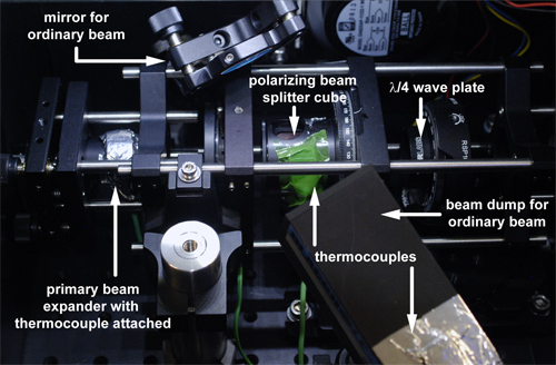
Figure 2. Top view of optical components for achieving circularly polarized light. This view includes the beam dump for the ordinary beam. As a safety measure, thermocouples are monitoring the temperature of the primary beam expander, the beam dump, and the polarizing beam splitter cube.
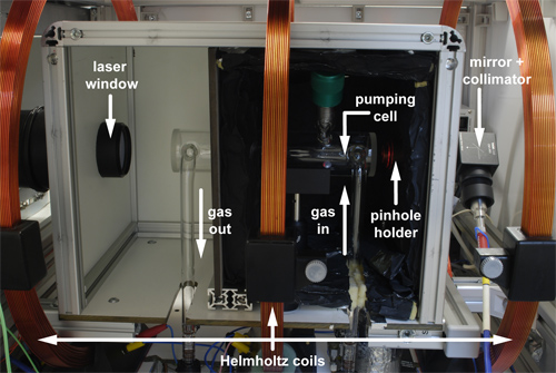
Figure 3. Side view of pumping cell with the side wall of the oven box opened. The laser light enters the box from the left through a parallel glass window. The pinhole on the right end attenuates the transmitted laser power to protect the optical spectrometer which receives the light through a collimator and optical fiber. The Xe gas mixture travels opposite to the laser light direction: it enters the cell through the right leg and exits on the left side.
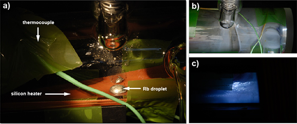
Figure 4. a) Close-up view of Rb droplet inside the pumping cell. The orange silicon heater (controlled by a PID regulator) is attached to the bottom of the glass cell. A thermocouple on top monitors the cell temperature. b) Close-up view of the gas inlet area of a medium aged pumping cell with increasing condensate build-up on the glass wall. c) Remaining Rb droplet in same pumping cell as in b), as seen by illuminating the cell from the back and with short exposure time to suppress visibility of the glass wall coating.
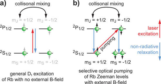
Figure 5. Energy transitions in alkali metal vapor. a) Without external B-field, the magnetic sub-levels are not defined (illustrated in grey only); hence any atom in the ground state absorbs light. b) Turning on an external field defines the Zeeman levels and causes pumping of only one transition according to the dipole selection rules. This causes accumulation of atoms in one of the sub-levels while a reduced number of atoms in the other ground state sub-level absorbs laser light.

Figure 6. Functionalized cryptophane cage for detecting a specific target of biochemical interest. The Xe NMR signal will change upon the binding event of the specific targeting unit.
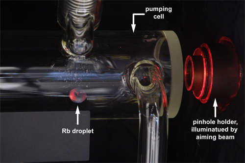
Figure 7. Visible aiming beam (red light) for alignment of the pumping cell to ensure complete illumination of the pumping volume.
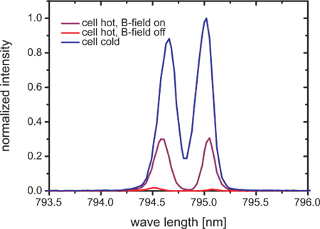
Figure 8. Laser profiles for different pumping cell conditions. No absorption is observed for the cold cell (room temperature) when no Rb vapor is present. We observe two emission lines from our diode laser (together with a FWHM of 0.5 nm that is within the manufacturer’s specification). When the cell reaches its set temperature (180 °C) and the magnetic field is turned off, general D1 excitation causes almost complete absorption of the laser light. Switching the magnetic field on induces selective pumping of only one transition and increases the transmission intensity.
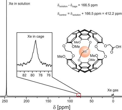
Figure 9. 129Xe NMR spectrum of a DMSO solution containing cryptophane-A monoacid (structure also shown) as a Xe cage. The gas peak is referenced to 0 ppm. Free Xe in solution appears at δsolution = 245.7 ppm and the caged Xe at δcage = 79.2 ppm. For the Hyper-CEST experiment, the saturation pulse is once set to δcage for enabling saturation transfer to decrease the solution peak and once set to δcontrol = 412.2 ppm to collect the reference signal for subtraction. Experimental parameters: 213 μM cage in DMSO at 295 K, 16 acquisitions with 32.3 kHz band width, 772 ms FID read out, Xe bubbled into solution at 0.1 SLM for 20 sec.

Figure 10. 129Xe MR images of xenon dissolved in DMSO. The phantom consists of two separate compartments with only the inner compartment containing cryptophane-A monoacid (at a concentration of 50 μM). Before each EPI image is taken, a 5 μT continuous-wave saturation pulse is applied for 2 sec. a) The saturation pulse is at δcontrol, i.e., off resonant with the Xe@cage peak and we observe strong signal from both compartments. b) The saturation is on resonant with the Xe@cage peak at δcage, almost completely destroying the signal from the inner compartment. The subtraction image a) – b) reveals the location of the Xe host molecule. The images were acquired with a FOV of 20 x 20 mm, a slice thickness of 10 mm and 32 x 32 pixels. They were then thresholded and interpolated to 256 x 256 pixels.
Movie 1. Animation of assembling a setup for SEOP. The laser beam is first increased in diameter by a primary beam expander and passes through a polarizing beam splitter cube (PBC). Rotation of this cube changes the relative intensities of the ordinary and extra-ordinary beam. For the position with maximum transmission, the fast axis of the PBC is aligned with the dominant polarization axis of the incoming light. The linear polarization of the transmitted light – which is influenced by the quality/extinction ratio of the PBC – can be tested using a second PBC as an analyzer. Aligning its fast axis with the fast axis of the first cube should give maximum transmission whereas further rotation by 90 ° should give zero transmission and full reflection. Insertion of a λ/4 wave plate converts the linear into circular polarization if its fast axis is rotated 45 ° against the fast axis of the first PBC. The intensity of the transmitted light should now be independent of the rotation of the second cube. Removing the analyzing components and replacing them with a secondary beam expander yields the right beam diameter to illuminate the pumping cell. A rubidium droplet sitting in this cell is partially vaporized once a heater outside the cell is turned on. The xenon gas mixture flowing through the setup in opposite direction to the laser beam distributes this vapor all over the cell. Without a magnetic field, this causes general D1 excitation of the Rb atoms and strong absorption of the laser light. Turning the magnetic on allows for selective pumping of only one transition between the now defined magnetic sub-levels. As a consequence, only a reduced number of atoms absorb the laser light and transmission is increased again. Click here to view movie.
Movie 2. Animation explaining the CEST effect. Cryptophane cages serve as molecular hosts to trap Xe atoms which change their resonance frequency upon this binding event (transition blue -> green). A first NMR acquisition determines the amount of unbound Xe as a reference signal. Next, a selective saturation pulse affecting only the caged atoms destroys their magnetization. Since the Xe binding is a reversible process, a long pulse cancels the magnetization of many atoms and a second NMR acquisition reveals a significant signal decrease from free Xe compared to the reference signal. Click here to view movie.
Discussion
Critical aspects in the preparation of hyperpolarized xenon are oxygen impurities in the gas manifold including the pumping cell and sufficient illumination of the cell with circularly polarized light. The above mentioned light bulb test is a simple way to detect deleterious oxygen concentrations while transferring rubidium. The alkali metal might loose its shiny surface by the time the cell is installed in the polarizer. However, sufficient vaporization of non-oxidized Rb can be monitored by reduced laser transmission (when heating a fresh cell for the first time, it could be that an additional temperature increase of ca. 20 °C is required to start the vaporization process; once laser absorption starts, the set point should be reduced). Almost complete laser absorption in the presence of the magnetic field indicates that there exists at least one region in the cell with excess Rb vapor densities that may cause inhomogeneous cell illumination and bad Xe hyperpolarization. Reduce temperature of the heater if this happens until there is approximately 30 % transmission through the cell.
Optimal temperature, pressure, gas mixture and flow rates have to be experimentally determined for each setup as these will depend on the specific geometry and thermal conduction of the optical cell and laser line width and power of individual polarizers. In particular it has been shown that spin exchange from Rb to Xe is most efficient at low pressure 12. Yet, due to the relatively large line width of diode lasers, Rb polarization is often more efficient at large pressures 1. These two factors must be played off against each other to reach maximum polarization for a given setup.
Alternative optical pumping can be achieved by using the Rb D2 transition with a laser emitting at 780 nm or by using Cs with its D1 transition at 894 nm 13 and D2 transition at 852 nm 14. Depending on the availability of laser systems, one of the four approaches can be chosen for optimal pumping conditions.
A good trouble shooting list for setting up and operating a SEOP setup can also be found in 15. Some more components for controlling vacuum and overpressure in the polarizer manifold and the evacuation stand used in step 3.5 are listed in the equipment table.
To preserve the polarization of the Xe, it must be kept in a magnetic field. The stray field of an NMR spectrometer is sufficient for this. In the gas phase the T1 of Xe is many hr. This can be increased by freezing the sample, which is particularly advantageous for transportation. Wall interactions are one of the major causes of depolarization of Xe gas. These can be reduced by careful selection of materials (e.g. by coating the glassware 16) and reducing the contact area between the gas and its container.
Acquisition of NMR data from solutions may be hampered by excessive foaming during the bubbling period or bubbles remaining in the liquid after the waiting delay. This causes serious field inhomogeneities and substantial signal loss. Reduce the set point of the mass flow controller in this case.
The polarization setup presented here allows for easy NMR studies with hyperpolarized xenon over extended periods of time. Hence, signal averaging for conditions with low target concentrations is easily possible. Signal stability is guaranteed through the use of mass flow controllers triggered by the spectrometer.
The signal of functionalized Xe has been reported to depend on several aspects of the micro-environment, including parameters like local temperature, pH and composition of the solvent. Therefore this approach has various potential applications in both in vitro and in vivo diagnostics.
Disclosures
The authors have nothing to disclose.
Acknowledgements
This research project has received funding from the European Research Council under the European Community’s Seventh Framework Programme (FP7/2007-2013) / ERC grant agreement n ° 242710 and was additionally supported by the Human Frontier Science Program and the Emmy Noether Program of the German Research Foundation (SCHR 995/2-1).
Materials
| Name of the reagent | Company | Catalogue number | Comments (optional) |
| Rb ingot | Sigma-Aldrich | 276332-1G | |
| P4O10 | Sigma-Aldrich | 79610-500G | |
| Ar | Praxair | ||
| Xe | Sigma-Aldrich | 00472-1EA | |
| O2 | Sigma-Aldrich | 00476-1EA | |
| Laser system | QPC Lasers/Laser Operations | Brightlock 50 | |
| Vacuum system | Pfeiffer | HiCube | |
| Thermocouples | Newport Omega | SA2F-KI-3M | |
| Silicon heater | Newport Omega | FMA5514 | |
| Pressure transducer | Newport Omega | PR 33X-V-10 | |
| Process meter | Newport Omega | INFCP-100B | |
| Mass flow controllers | Newport Omega | MFC | |
| PID regulators | Newport Omega | CN7800 | |
| Control Software | Newport Omega | DasyLab | |
| Data acquisition | Newport Omega | Daqboard 3000 | |
| Vacuum sensor | Oerlikon | TTR91 | |
| Vacuum controller | Vacom | MVC-3 | |
| Beam collimator | Thorlabs | F810SMA-780 | |
| Polarizing beam splitter cube | Thorlabs | GL15-B | |
| λ/4 wave plate | Thorlabs | WPQ10M-780 | |
| Beam expansion lenses | Thorlabs | ||
| Optical spectrometer | Ocean Optics | HR4000 | |
| Optical fiber | Ocean Optics | ||
| Low pressure NMR tube | Wilmad | 513-7LPV-7 | |
| 5mm NMR tube | Sigma-Aldrich | HX58.1 | |
| Helmholtz coils | Phywe | 06960-00 | |
| Fused silica capillaries | Polymicro | TSG 250350 |
References
- Schröder, L. Xenon for NMR biosensing – Inert but alert. Phys Med. , (2011).
- Viale, A., Reineri, F., Santelia, D., Cerutti, E., Ellena, S., Gobetto, R., Aime, S. Hyperpolarized agents for advanced MRI investigations. Q J Nucl. Med. Mol. Imaging. 53, 604-617 (2009).
- Walker, T. G., Happer, W. Spin-exchange optical pumping of noble-gas nuclei. Rev. Mod. Phys. 69, 629-642 (1997).
- Albert, M. S., Cates, G. D., Driehuys, B., Happer, W., Saam, B., Springer, C. S., Wishnia, A. Biological magnetic resonance imaging using laser-polarized 129Xe. Nature. 370, 199-201 (1994).
- Cherubini, A., Bifone, A. Hyperpolarised xenon in biology. Progr. NMR Spectrosc. 42, 1-30 (2003).
- Goodson, B. M. Nuclear magnetic resonance of laser-polarized noble gases in molecules, materials, and organisms. J. Magn. Reson. 155, 157-216 (2002).
- Nikolaou, P., Whiting, N., Eschmann, N. A., Chaffee, K. E., Goodson, B. M., Barlow, M. J. Generation of laser-polarized xenon using fiber-coupled laser-diode arrays narrowed with integrated volume holographic gratings. J. Magn. Reson. 197, 249-254 (2009).
- Ruppert, K., Brookeman, J. R., Hagspiel, K. D., Mugler, J. P. Probing lung physiology with xenon polarization transfer contrast (XTC). Magn. Reson. Med. 44, 349-357 (2000).
- Driehuys, B., Cofer, G. P., Pollaro, J., Mackel, J. B., Hedlund, L. W., Johnson, G. A. Imaging alveolar-capillary gas transfer using hyperpolarized 129Xe MRI. Proc. Natl. Acad. Sci. U.S.A. 103, 18278-18283 (2006).
- Spence, M. M., Rubin, S. M., Dimitrov, I. E., Ruiz, E. J., Wemmer, D. E., Pines, A., Yao, S. Q., Tian, F., Schultz, P. G. Functionalized xenon as a biosensor. Proc. Natl. Acad. Sci. U.S.A. 98, 10654-10657 (2001).
- Schröder, L., Lowery, T. J., Hilty, C., Wemmer, D. E., Pines, A. Molecular imaging using a targeted magnetic resonance hyperpolarized biosensor. Science. 314, 446-449 (2006).
- Schrank, G., Ma, Z., Schoeck, A., Saam, B. Characterization of a low-pressure high-capacity 129Xe flow-through polarizer. Phys. Rev. A. 80, 063424 (2009).
- Levron, D., Walter, D. K., Appelt, S., Fitzgerald, R. J., Kahn, D., Korbly, S. E., Sauer, K. E., Happer, W., Earles, T. L., Mawst, L. J., Botez, D., Harvey, M., DiMarco, L., Connolly, J. C., Möller, H. E., Chen, X. J., Cofer, G. P., Johnson, G. A. Magnetic resonance imaging of hyperpolarized 129Xe produced by spin exchange with diode-laser pumped Cs. Appl. Phys. Lett. 73, 2666 (1998).
- Zhou, X., Sun, X. P., Luo, J., Zeng, X. Z., Liu, M. L., Zhan, M. S. Production of Hyperpolarized 129Xe Gas Without Nitrogen by Optical Pumping at 133Cs D2 Line in Flow System. Chin. Phys. Lett. 21, 1501-1503 (2004).
- Zhou, X. Hyperpolarized noble gases as contrast agents. Methods Mol. Biol. 771, 189-204 (2011).
- Seltzer, S. J., Michalak, D. J., Donaldson, M. H., Balabas, M. V., Barber, S. K., Bernasek, S. L., Bouchiat, M. A., Hexemer, A., Hibberd, A. M., Kimball, D. F., Jaye, C., Karaulanov, T. Investigation of antirelaxation coatings for alkali-metal vapor cells using surface science techniques. J. Chem. Phys. 133, 144703 (2010).

