Acute Single-Unit Multi-Electrode Recordings from the Brainstem of Head-Fixed Mice
Summary
This protocol describes a method to obtain in vivo, high-density single-neuron recordings from the brainstem of head-fixed mice. This approach is deployed to measure the action potential firing of neurons in the ventrolateral periaqueductal gray – a brainstem region inactive during Rapid Eye Movement (REM) sleep – before and during general anesthesia.
Abstract
Silicon multielectrode-based recordings are increasingly popular for studying neuronal activity at the temporal resolution of action potentials in many brain regions. However, recording neuronal activity from deep caudal structures like the brainstem using multi-channel probes remains challenging. A significant concern is finding a trajectory for probe insertion that avoids large blood vessels, such as the superior sagittal venous sinus and the transverse venous sinus. Injuring these large veins can cause extensive bleeding, damage to the underlying brain tissue, and potentially death. This approach describes targeting brainstem structures by coupling anterior coordinates with an angled approach, allowing the recording probe to penetrate the brain below high-risk vascular structures. Compared to a strictly vertical approach, the angled approach maximizes the number of brain regions that can be targeted. Using this strategy, the ventrolateral periaqueductal gray (vlPAG), a brainstem region associated with REM sleep, can be reproducibly and reliably accessed to obtain single-unit, multi-electrode recordings in head-fixed mice before and during sevoflurane anesthesia. The ability to record neuronal activity in the vlPAG and surrounding nuclei with high temporal resolution is a step forward in advancing the understanding of the relationship between REM sleep and anesthesia.
Introduction
Silicon multielectrode-based recordings are becoming increasingly popular to measure neuronal activity across many brain regions with single action potential resolution1,2,3,4. Over the last decade, high-density recording technology has grown considerably. Current silicon-based recording electrodes can accommodate high channel counts, optical fibers, and electrocorticography (ECoG) recording devices5,6. Moreover, chronic implantation of these electrodes allows for long-term recordings7,8.
Despite recent technological advancements, targeting deep caudal structures like the brainstem with multi-channel probes remains challenging. When targeting brainstem structures such as the ventrolateral periacqueductal gray (vlPAG), one significant obstacle is identifying a probe trajectory that avoids major blood vessels, e.g., the superior sagittal venous sinus and the transverse venous sinus. Injury to these large veins can cause extensive bleeding, damage to the underlying brain tissue, and even death9,10. We propose targeting brainstem structures from anterior coordinates at an angle, allowing the recording probe to penetrate the brain below such high-risk vascular structures (see Figure 1). This angled approach, compared to a vertical one, maximizes the number of brain regions accessible for recording. Additionally, in experimental circumstances wherein ECoG recordings are desired, the angled anterior approach affords more skull surface available for ECoG headset implantation, as the craniotomy window for probe insertion is positioned more anteriorly10,11.
Identifying the specific cell groups and circuits responsible for anesthesia-induced REM sleep changes remains a major goal of anesthesia research. Thus, the objective here was to reproducibly and reliably access the vlPAG – a brainstem region associated with REM sleep – to obtain single unit, multi-electrode recordings in head-fixed mice before and during sevoflurane anesthesia12,13. Previous studies have used electrophysiological local field potential (LFP) measurements of the vlPAG in awake mice to identify neural state changes associated with anesthesia14,15. However, LFP measurements are primarily sensitive to synaptic activity, not action potentials, within the recorded area16. Consequently, there remains a limited understanding of how anesthetics directly affect the neural activity patterns produced by vlPAG neurons. Here, a method is described to obtain high-density single-neuron recordings from the brainstem of head-fixed mice. This method can also be adapted to record single-neuron activity from various other deep and posterior brainstem structures.
Protocol
All studies were approved by the Institutional Animal Care and Use Committee at the University of Virginia (Charlottesville, Virginia). Five male C57BL/6J mice, age 3-7 months, weighing 25-30 g, were used. The details of the reagents and the equipment used here are listed in the Table of Materials.
1. Headplate and headset implantation
- Make an ECoG headset by soldering perfluoroalkoxy (PFA) coated stainless steel wire to a 3-pin connector header (Figure 2A).
- Identify the insertion coordinates based on a mouse stereotaxic atlas17. Using the Pythagorean theorem to calculate the angle and depth of probe insertion -particularly when there is little information in the literature -is a reasonable starting point (Figure 1)18.
NOTE: Ultimately, coordinates will be adjusted by trial and error. To target the vlPAG the following coordinates were used in adult mice: anteroposterior (AP) -3.6 mm, mediolateral (ML) +0.5 mm, dorsoventral (DV) -4 mm. The probe was inserted at a 20° angle (AP). - Induce general anesthesia by placing the mouse in the induction chamber (1.5%-3% Isoflurane in oxygen). Once anesthetized, position the mouse in the stereotaxic frame, placing the animal's nose in the nose cone and stabilizing the head with head bars.
- Apply ophthalmic ointment to the eyes to prevent corneal damage. Use a temperature control system to maintain body temperature at 37 °C.
- Apply hair removal cream or shave fur over the scalp, then disinfect with povidone iodine and 70% alcohol.
- Perform a toe pinch test to check the depth of anesthesia.
- Administer analgesia: carprofen 2.5 mg/kg, given subcutaneously in the back.
- Make a 5 mm scalp incision to remove a circular patch of skin above the parietal and occipital bones. Gently remove the meninges by scraping them with the scalpel blade.
- Use the scalpel blade to cut muscle attachments and expose the parietal and occipital bones19. Apply hydrogen peroxide as needed to control bleeding and dry the skull surface. It is crucial to apply dental cement and resin on dry skull to achieve a strong bond.
- First, identify the bregma and lambda landmarks on the skull20. Then, adjust the nose cone position to level the anterior-posterior position of the skull, ensuring that no more than 100 µm height difference exists between the two landmarks.
- To level the medial-lateral position of the skull, pick two opposite points between bregma and lambda, each one 1mm from the sagittal suture and check their level. If there's more than 100 µm height difference between them, adjust the medial-lateral position of the skull by manipulating the head bars.
- Measure the distance between bregma and lambda and compare it to the distance reported in Franklin-Paxinos stereotaxic atlas (usually 4.2 mm)17. Use the difference between the measured and reported distances to scale your AP coordinate proportionally. Mark craniotomy coordinates on the skull with a sterilized pencil.
NOTE: If the measured bregma-lambda distance differs from 4.2 mm, then the coordinates need to be scaled proportionately. All AP coordinates reported in a stereotaxic atlas correspond to a standardized bregma-lambda distance. Because the size of a mouse skull is variable, it is important to adjust your coordinates accordingly. - Using a stereotaxic micromanipulator, position the headplate directly on top of the lambda suture, and secure it to the skull by applying dental cement on the headplate and around it (Figure 3A,B). Allow at least 10 min for the cement to dry.
- Drill burr holes (0.5 mm in diameter) for two cortical electrodes (frontal and parietal cortex) and for one that will serve as a reference electrode (cerebellum). Place the stripped ends (0.5 mm) of coated silver wire electrodes within the burr holes and secure using ultraviolet light-activated resin.
- Completely cover the coated stainless-steel wires with dental cement so that no wire is exposed. Cover the underside and sides of the headset with dental cement so that it is firmly in place. Make sure bregma and lambda sutures remain visible once the headset is secured in place (Figure 2B).
- Let the mouse recover for a minimum of 7 days, examine the animal and surgical site daily for any irregularities. Administer analgesics (Carprofen 2.5 mg/kg, SC) as needed.
2. Silicon probe placement and recording
- Habituate the mouse to the recording rig and head fixation (at least 1.5 h on two separate days) (Figure 2D).
- On the day of the recording, place the mouse in the anesthesia chamber (Isoflurane 1.5%-3% in oxygen).
- Position the mouse in a stereotaxic frame, adjust nose cone and head bars as described in 1.3.
- Apply ophthalmic ointment to the eyes and maintain adequate body temperature.
- Identify bregma and lambda, ensuring that no more than 100 µm height difference exists between the two anatomical landmarks.
- Find and mark the calculated coordinates on the skull with a sterile pencil, then create an outline of the 2 mm x 2 mm craniotomy window around the coordinates.
- Perform a toe pinch test to check anesthesia depth.
- Use a high-speed drill to create a 2 mm x 2 mm craniotomy window. Apply 0.5-1 mL of normal saline to prevent brain surface from drying. Remove the dura using a syringe needle and fine forceps.
NOTE: Watch for major vessels (superior sagittal sinus, transverse sinus) to avoid excessive bleeding (Figure 3). - Use a high-speed drill to create a separate burr hole for the silicon probe's reference electrode, generally ~1-2 mm from the cranial window.
- Apply 0.2 mL low toxicity silicon adhesive on the skull to completely seal the craniotomy, using the attached applicator.
- Let the mouse recover for approximately 1 h.
- Affix the head of the mouse to the electrophysiology recording rig using the headplate and screws (Figure 2D).
- Coat the silicon probe shank with the fluorescent dye DiI (1:4 DiI:Ethanol) so that the probe trajectory can be reconstructed after the experiment.
- Mount the probe on the manipulator and set the desired angle. To target the vlPAG, an AP angle of 15-20° was applied.
- Lower the recording probe to the brain surface within the center of the cranial window. First, manually insert the probe to a depth of ~300 µm. Once inserted to this depth, slowly lower the probe automatically (e.g., 200 µm/min) to the targeted depth to minimize tissue damage21 (Figure 2C).
NOTE: Manual insertion of the probe is initially recommended. Manual probe insertion ensures the ability to stop and retract the probe should it bend upon initial insertion. Once the probe fully penetrates the tissue, it is generally safe to continue descending the probe in automatic mode. - Apply mineral oil to the brain surface within the craniotomy window to prevent from drying.
- Let the recording probe settle for 10 min after insertion.
- Record data from the silicon probe and ECoG at 30kHz using an Intan Recording Controller.
- 1-2 h after recording, use the transcardial perfusion technique to fix the brain in 4% paraformaldehyde22.
NOTE: Because of the cement, it might be difficult to remove the rostral part of the skull. That's why it is preferable to excise the brain by removing the dorsal parts of the skull. - Decapitate the mouse, cut the skin following the midline on the dorsal side, from the neck to the bottom jaw. Remove muscles and tissue attached to the skull, cut off the bottom jaw for easier access to the brain.
- If the perfusion is done correctly the brain should shrink a little, leaving enough space to insert fine scissors in the dorsal part of the foramen magnum. Make one medial cut, one lateral and one contralateral cut, around 1 mm in size, in the occipital bone.
- Carefully remove the dorsal part of the skull using ophthalmic forceps. Start at the occipital bone, remove all skull fragments until the whole dorsal part of the brain is exposed.
- Slide a micro spatula under the brain, starting at the olfactory bulbs to scoop the brain out.
- Once perfused and removed, the brain can be stored in 4% paraformaldehyde at 4 °C for 24-48 h.
3. Histology for probe trajectory reconstruction
- Section the brain into 70 µm coronal sections using a vibratome.
- Mount the sections on slides using a DAPI mounting medium that stains cell nuclei. Coverslip and seal the slides with clear nail polish.
- Image the slides on a fluorescence microscope. Adjust contrast/brightness so that probe tracks are clearly visible. Ensure the resultant tiff image file sizes are less than 10 MB, so that MATLAB codes run smoothly. Reconstruct the probe tracks using a MATLAB code23.
4. Electrophysiological data analysis
- Analyze recorded neural signals from the silicon probe using an off-line detection and automatic sorting software (Kilosort)24.
- Manually classify detected clusters with Phy as multi- or single units25. Classify clusters as single units when they have a physiological spike waveform shape, show a refractory period in the cross-correlogram, and a normal distribution of amplitude view.
- Import single unit data to MATLAB and analyze23.
Representative Results
Five male C57BL/6J were implanted with an ECoG headset and headplate (Figure 4A). After recovery, mice were habituated to head-fixation and the electrophysiology recording rig during two 1.5 h sessions on separate days (Figure 4B). Next, a 2 mm x2 mm craniotomy window was created (Figure 4C) and a silicon probe was inserted with the mouse awake and head-fixed (Figure 4D). Two types of silicon UCLA probes were used: (1) 64 M: a one-shank, 64 electrode probe; and (2) 256 ANS: a four-shank, 256 electrode probe. Sevoflurane and oxygen were administered using a nose cone fixed to the electrophysiology rig. Levels of oxygen and sevoflurane were monitored every 5 min using an inline gas analyzer. Following transcardial perfusion, the brain was harvested (Figure 4E) and evaluated for probe trajectory (Figure 4F). Recorded action potentials were then curated into single unit data (Figure 4G).
Five recordings were performed wherein probe placement was validated with available probe reconstruction algorithms developed in MATLAB23. Using these algorithms, each electrode of the silicon probe was localized to a specific brain structure so that a three dimensional perspective of probe placement within the brain was acquired (Figure 5). These reconstruction algorithms were coupled with immunohistochemical markers to further validate probe trajectories (Figure 6). The data was then matched with curated single units (Figure 7).
A total of 64 single neurons was captured, of which 13 were located in the vlPAG. The remaining 51 neurons were in nearby nuclei: midbrain, midbrain reticular nucleus, paratrochlear nucleus, cuneiform nucleus, laterodorsdal tegmental nucleus, parabrachial nucleus, and superior cerebellar peduncles. The firing activity of neurons in each mouse is presented as heat maps (Figure 7). Mouse 3 was excluded from the analysis because of poor quality single-unit recording. Most recorded neurons decreased their firing during sevoflurane anesthesia.
Mean firing of vlPAG neurons was compared for each mouse at 5 min baseline (i.e., 10-15 min into the recording) and 5 min during sevoflurane (i.e., 40-45 min into the recording). vlPAG firing was significantly decreased (Figure 8A) and furthermore, this increase was consistent across all vlPAG neurons (Figure 8B).
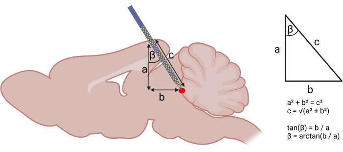
Figure 1: Calculating stereotaxic coordinates for probe insertion. Left panel: Using geometry to calculate angled approach for probe insertion. The following components of a right triangle were identified: (a) DV depth of the target structure from the brain surface (acquired using the stereotaxic atlas), (b) distance between the AP coordinate assuming a strictly vertical descent and the AP coordinate of the target structure. Right panel: With (a) and (b), one can use the Pythagorean theorem to calculate the AP angle (β) and length (c) of probe insertion. The following coordinates were used to target the vlPAG: (AP) -3.6 mm, (ML) +0.5 mm, (DV) -4 mm. An AP angle (β) of 20° was used. Please click here to view a larger version of this figure.
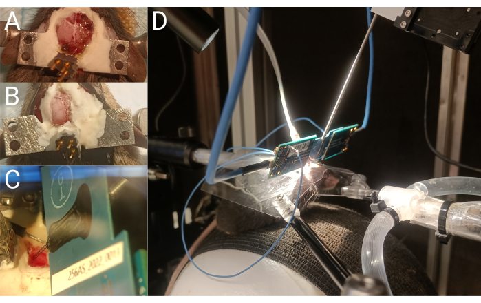
Figure 2: Headplate implantation and single unit recording. (A) ECoG headset wire placement during implantation. (B) Top view of the mouse skull after ECoG headset and headplate implantation. (C) Silicon probe shanks inserted into the brain.(D) Head-fixed mouse during a silicon probe recording. Please click here to view a larger version of this figure.
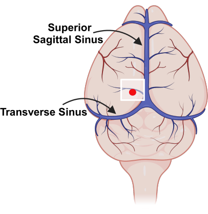
Figure 3: Placement of cranial window, relative to major blood vessels. Schematic representation of vasculature on the surface of the mouse brain with superior sagittal sinus and transverse sinus marked. The white square indicates the location of the cranial window and the red dot represents the probe insertion point. Please click here to view a larger version of this figure.
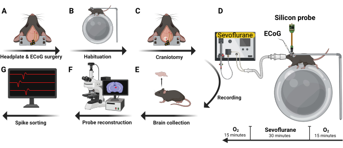
Figure 4: Experimental design. Five male C57BL/6J mice were implanted with ECoG headset and headplate (A). After recovery, they were habituated to head-fixation and the recording rig (B). Next, a craniotomy was performed (C) and a silicon probe inserted with the mouse awake and in a head-fixed position. Volatile anesthetics and oxygen were administered using a nose cone (D). After recording, the brain was harvested (E) and analyzed using immunohistochemistry techniques to reconstruct the trajectory of the probe (F). Recorded action potentials were then curated into single unit data (G). Please click here to view a larger version of this figure.
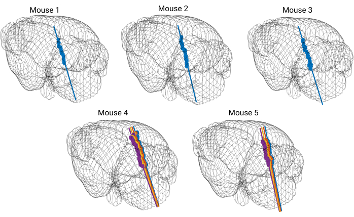
Figure 5: 3D model of the brain with reconstructed probe tracks. Each straight colored line represents a probe trajectory. Each dot marks the location of DiI dye visible on coronal brain slices. The probe trajectory is reconstructed for every shank of the silicon probe. Please click here to view a larger version of this figure.
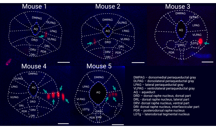
Figure 6: Post hoc reconstruction of probe placement within the vlPAG. Representative coronal brain slice for each recorded mouse (1-5) stained with DAPI (blue) showing probe tracks ((DiI, red, marked by green arrows) with an outline of brain regions. Scale bar: 500 µm. Mouse 1-3 were recorded with single shank silicon probes (i.e., 64 channels), whereas mouse 4 & 5 were recorded with four-shank silicon probes (i.e., 256 channels). Please click here to view a larger version of this figure.
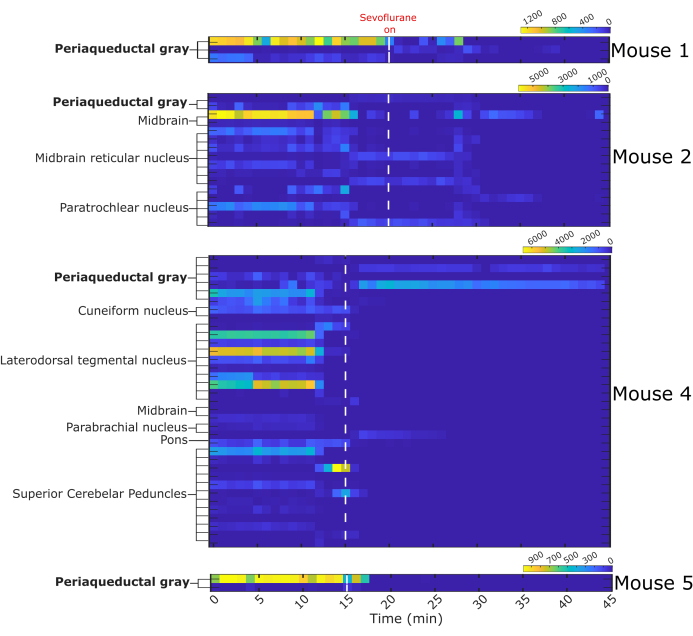
Figure 7: Binned firing activity before and during sevoflurane anesthesia. Heat maps represent the number of fired action potentials by 64 single neurons in one-minute intervals. Single neurons were assigned a structure of origin based on the probe trajectory reconstruction. White dashed line indicates start of sevoflurane administration, n = 4 mice. Please click here to view a larger version of this figure.
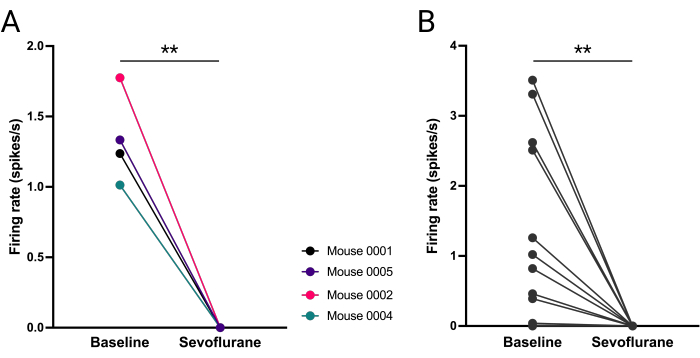
Figure 8: Abolished firing of vlPAG neurons during sevoflurane anesthesia. (A) Mean number of action potentials fired before and during anesthesia for each mouse. (B) Number of action potentials fired by each vlPAG neuron (B). Paired t-student test, **P = 0.0036, P = 0.0053 respectively. Please click here to view a larger version of this figure.

Figure 9: Example of how uneven headplate placement can affect probe trajectory. (A) Uneven placement of headplate on mouse head. (B,C) 3D mouse brain reconstruction with rendered probe trajectory where there is an unintentional mediolateral angle caused by uneven placement of headplates on mouse head. Please click here to view a larger version of this figure.
Discussion
Brainstem nuclei mediate fundamental functions such as breathing, consciousness, and sleep26,27,28. The brainstem's location (deep and posterior) presents a challenge in studying its neuronal activity in vivo using standard techniques. Here an angled anterior approach is presented to allow reproducible single unit recording in head-fixed mice.
Careful insertion of the multi-electrode silicon probe is critical to ensure consistent targeting of brainstem structures related to REM sleep, while avoiding damage to major blood vessels. A considerable degree of finesse, concentration and patience are required to resolve the best coordinates and trajectory of entry13.
Because of the angled probe trajectory and the distance required to target deep structures, even minor inconsistencies in coordinates and headplate positioning will likely result in missing the target structure. It is imperative that Bregma and Lambda are on the same level during headplate implantation and that the distance between them is precisely measured. Notably, because surgeries are performed on a stereotaxic frame and recordings are performed on a separate electrophysiology rig, it is critical for the headplates to be fixed to a leveled skull. Introducing additional angles (i.e., tilted head) increases the risk of error, which is particularly high for small, deep brain structures (Figure 9).
Since silicon probes are fragile, it is important to remove the dura from the surface of the brain and to make sure no bone fragments are obstructing the cranial window. Light bleeding may occur after dura removal, so it is crucial to clear the craniotomy surface of congealed blood that might cause the probe to bend. If inserting the silicon probe into the brain proves difficult (e.g., the probe is bending), it is important to check for any remaining dura or if the brain's surface has dried, as a thin membrane can form when left with little to no liquid. In humans27, areas close to blood vessels have a thicker dura, and a similar issue is found in mice, where removing the dura without rupturing vessels can be challenging. Although careful removal of the dura usually results in smooth probe insertion, larger insertion angles may present additional difficulties.
The yield of recordings can vary considerably between animals and depends on numerous variables. One significant factor is the density of neurons in the targeted structure; areas with low neuron density (e.g., cortex) tend to have a lower yield of recorded single neurons. Additionally, tissue damage, such as rupturing a vessel beneath the brain surface, can lead to neuronal death or injury, further reducing yield21,29. The quality of the recordings is also crucial, as higher quality recordings make it easier to distinguish single neurons. An off-target probe trajectory can also result in lower yields. Although developed for recordings in the vlPAG, this protocol can be used to record from nearby structures in the brainstem.
Divulgations
The authors have nothing to disclose.
Acknowledgements
Figure 1, Figure 3, Figure 4, Figure 8 and Figure 9 were created with BioRender.com. We would like to thank Scott Kilianski for the help with MATLAB code and sharing his scripts. We thank Anna Grace Carns for the help with probe trajectory reconstruction.
Materials
| 1024 channel RHD Recording Controller | Intan Technologies, Los Angeles, California, USA | C3008 | Silicon probe recording; recording hardware and software | |
| 24 mm x 50 mm No. 1.5 VWR coverslip | VWR, Radnor, Pennsylvania, USA | 48393-081 | Histology | |
| 4% PFA in PBS | ThermoFisher Scientific, Waltham, Massachusetts, USA | J61899.AK | Histology; perfusion solution | |
| C&B metabond | Patterson Dental, Richmond, Virginia, USA | powder: 5533559, quick base: 5533492, catalyst: 55335007 | Headplate &Headset Implantation | |
| C57/6J mice 4-6 weeks, males | The Jackson Laboratory, Bar Harbor, Maine, USA | 000664 | ||
| Capnomac Ultima | Datex, Helsinki, Finland | ULT-SVi-27-07 | Gas Analyzer; discontinued; alternative gas analyzer can be purchased from Bionet America | |
| CM-DiI | ThermoFisher Scientific, Waltham, Massachusetts, USA | V22888 | Red fluorescent dye for coating of the silicon probe | |
| Connector Header | DigiKey, Thief River Falls, Minnesota, USA | 1212-1788-ND | ECoG Headset | |
| DAPI Fluoromount-G | SouthernBiotech, Birmingham, Alabama, USA | 0100-20 | Histology | |
| iBOND Universal | Patterson Dental, Richmond, Virginia, USA | 044-1113 | Headplate &Headset Implantation; for securing stainless steel wires to the skull | |
| Low toxicity silicon adhesive | World Precision Instruments, Sarasota, Florida, USA | KWIK-SIL | Headplate | |
| Micro-Manipulator System | New Scale Technologies, Victor, New York, USA | Multi-Probe Manipulator: XYZ Stage Assembly: 06464-0000, MPM System Kit: 06267-3-0001, MPM-Platform-360, MPM ring for MPM Manual Arms, MPM_Ring-72 DEG: 06262-3-0000 | Silicon probe recording; inserting the probe into the brain | |
| Microprobes | UCLA, Los Angeles, California, USA | 256 ANS, 64M | Discontinued; alternative silicon probes can be purchased from Neuropixels | |
| Mineral Oil | Sigma Aldrich, Saint Luis, Missouri, USA | M8410-100ML | Silicon probe recording; preventing the tissue from drying during the recording | |
| Normal saline | ThermoFisher Scientific, Waltham, Massachusetts, USA | Z1376 | Headplate &Headset Implantation; preventing the brain from drying during the surgery | |
| PFA-Coated Stainless Steel Wire-Diameter 0.008 in. coated with striped ends | A-M systems, Sequim, Washington, USA | 791400 | ECoG Headset & reference electrode for ECoG | |
| Platinum wire 24AWG | World Precision Instruments, Sarasota, Florida, USA | PTP201 | Reference electrode for the silicon probe recording | |
| Shandon Colorfrost Plus microscope slides | ThermoFisher Scientific, Waltham, Massachusetts, USA | 99-910-01 | Histology | |
| Stainless steel Headplate | Star Rapid, China | custom made part | Headplate &Headset Implantation; design available upon request | |
| Stereotaxic apparatus | KOPF, Tujunga, California, USA | Model 940 Small Animal Stereotaxic Instrument with Digital Display Console | Headplate &Headset Implantation |
References
- Wu, F., et al. Monolithically integrated µLEDs on silicon neural probes for high-resolution optogenetic studies in behaving animals. Neuron. 88 (6), 1136-1148 (2015).
- Hong, G., Lieber, C. M. Novel electrode technologies for neural recordings. Nat Rev Neurosci. 20 (6), 330-345 (2019).
- Li, N., Daie, K., Svoboda, K., Druckmann, S. Robust neuronal dynamics in premotor cortex during motor planning. Nature. 532 (7600), 459-464 (2016).
- Kipke, D. R., et al. Advanced neurotechnologies for chronic neural interfaces: New horizons and clinical opportunities. J Neurosci. 28 (46), 11830-11838 (2008).
- Steinmetz, N. A., Koch, C., Harris, K. D., Carandini, M. Challenges and opportunities for large-scale electrophysiology with Neuropixels probes. Curr Opinion Neurobiol. 50, 92-100 (2018).
- Nunez-Elizalde, A. O., et al. Neural correlates of blood flow measured by ultrasound. Neuron. 110 (10), 1631-1640.e4 (2022).
- Yang, L., Lee, K., Villagracia, J., Masmanidis, S. C. Open source silicon microprobes for high throughput neural recording. J Neural Eng. 17 (1), 016036 (2020).
- Jun, J. J., et al. Fully integrated silicon probes for high-density recording of neural activity. Nature. 551 (7679), 232-236 (2017).
- Augustinaite, S., Kuhn, B. Chronic cranial window for imaging cortical activity in head-fixed mice. STAR Protoc. 1 (3), 100194 (2020).
- Dias, M., et al. Transection of the superior sagittal sinus enables bilateral access to the rodent midline brain structures. eNeuro. 8 (4), (2021).
- Gao, Z. R., et al. Tac1-expressing neurons in the periaqueductal gray facilitate the itch-scratching cycle via descending regulation. Neuron. 101 (1), 45-59.e9 (2019).
- Atluri, N., et al. Anatomical substrates of rapid eye movement sleep rebound in a rodent model of post-sevoflurane sleep disruption. Anesthesiology. 140 (4), 729-741 (2023).
- Weber, F., Dan, Y. Circuit-based interrogation of sleep control. Nature. 538 (7623), 51-59 (2016).
- Frontera, J., et al. Bidirectional control of fear memories by cerebellar neurons projecting to the ventrolateral periaqueductal grey. Nat Commun. 11 (1234567890), (2020).
- Weber, F., et al. Regulation of REM and Non-REM sleep by periaqueductal GABAergic neurons. Nat Commun. 9 (1), 354 (2018).
- Buzsáki, G., Anastassiou, C. A., Koch, C. The origin of extracellular fields and currents–EEG, ECoG, LFP and spikes. Nat Rev Neurosci. 13 (6), 407-420 (2012).
- Franklin, K. B. J., Paxinos, G. . The mouse brain in stereotaxic coordinates. , (2008).
- . Pythagorean theorem Available from: https://en.wikipedia.org/w/index.php?title=Pythagorean_theorem&oldid=1222259845 (2024)
- . The Anatomy of the Laboratory Mouse Available from: https://www.informatics.jax.org/cookbook/chapters/skeleton.shtml (2024)
- Cecyn, M. N., Abrahao, K. P. Where do you measure the Bregma for rodent stereotaxic surgery. IBRO Neurosci Rep. 15, 143-148 (2023).
- Fiáth, R., et al. Slow insertion of silicon probes improves the quality of acute neuronal recordings. Sci Rep. 9, 111 (2019).
- Wu, J., et al. Transcardiac perfusion of the mouse for brain tissue dissection and fixation. Bio-protocol. 11 (5), e3988 (2021).
- Peters, A. . petersaj/AP_histology. , (2024).
- Pachitariu, M., Sridhar, S., Stringer, C. . Solving the spike sorting problem with Kilosort. , (2023).
- Akam, T., Walton, M. E. pyPhotometry: Open source Python based hardware and software for fiber photometry data acquisition. Sci Rep. 9 (1), 3521 (2019).
- Leiras, R., Cregg, J. M., Kiehn, O. Brainstem circuits for locomotion. Ann Rev Neurosci. 45 (2022), 63-85 (2022).
- Benarroch, E. E. Brainstem integration of arousal, sleep, cardiovascular, and respiratory control. Neurology. 91 (21), 958-966 (2018).
- Guyenet, P. G., Bayliss, D. A. Neural control of breathing and CO2 homeostasis. Neuron. 87 (5), 946-961 (2015).
- Potter, K. A., Buck, A. C., Self, W. K., Capadona, J. R. Stab injury and device implantation within the brain results in inversely multiphasic neuroinflammatory and neurodegenerative responses. J Neural Eng. 9 (4), 046020 (2012).

.
