C. elegans Tracking and Behavioral Measurement
Summary
We have developed a video-rate tracking microscope system that can record and quantify C. elegans behavior at high resolution and high speeds. We have also developed computational methods to reduce the dimensionality of the worm images to a fundamental set of measurements that completely describe the shape of the worm.
Abstract
We have developed instrumentation, image processing, and data analysis techniques to quantify the locomotory behavior of C. elegans as it crawls on the surface of an agar plate. For the study of the genetic, biochemical, and neuronal basis of behavior, C. elegans is an ideal organism because it is genetically tractable, amenable to microscopy, and shows a number of complex behaviors, including taxis, learning, and social interaction1,2. Behavioral analysis based on tracking the movements of worms as they crawl on agar plates have been particularly useful in the study of sensory behavior3, locomotion4, and general mutational phenotyping5. Our system works by moving the camera and illumination system as the worms crawls on a stationary agar plate, which ensures no mechanical stimulus is transmitted to the worm. Our tracking system is easy to use and includes a semi-automatic calibration feature. A challenge of all video tracking systems is that it generates an enormous amount of data that is intrinsically high dimensional. Our image processing and data analysis programs deal with this challenge by reducing the worms shape into a set of independent components, which comprehensively reconstruct the worms behavior as a function of only 3-4 dimensions6,7. As an example of the process we show that the worm enters and exits its reversal state in a phase specific manner.
Protocol
1. Description of Tracking Microscope
- An agar plate is illuminated by a fiber light source and imaged with a camera. This system is mounted to an X,Y translation stage.
- The stage is moved by standard stepper motors, which are connected to a stepper motor controller.
- The controller and camera are connected to the computer and controlled by custom programs written in LabVIEW.
- The camera images the surface of an agar plate and identifies dark objects on a light background.
- The image quality is adjusted so that computer program can quantify objects in real time. The gain, brightness, and shutter speed of the camera can be adjusted to provide a dark object on a white background.
- A calibration mark for the automatic calibration process is made by poking the agar surface with a worm pick.
- The filtered, binary image which is used by the tracking program can be checked.
- The software has an auto-calibration feature that calculates the calibration matrix by moving a test object a fixed distance.
- Distances in pixels is calibrated to steps taken by the stepper motor by the calibration matrix.
- After calibration, the system is ready to go and does not need to be recalibrated unless the magnification is changed or if the camera is repositioned.
2. Preparing Tracking Plates and C. elegans for Tracking
- A copper ring is used to corral the worms and keep them from migrating to the edge of the plate. The copper provides a local chemical barrier and does not affect movement of the worm otherwise for the duration of the experiment (<1 hr). Heat the ring first by placing it on a heat block or equivalent.
- Place ring onto a fresh agar plate (1.7% Bacto Agar, 0.25% Bacto-Peptone, 0.3% NaCl, 1 mM CaCl2, 1 mM MgSO4, 25 mM potassium phosphate buffer, 5 μg/ml cholesterol) and press down slightly to embed it into the agar surface.
- Pick L4 stage or young adult worms onto an agar plate filled with some NGM buffer (0.3% NaCl, 1 mM CaCl2, 1 mM MgSO4, 25 mM potassium phosphate buffer) to wash them of food residue. Let the worms swim for a few minutes.
- Carefully place a single worm onto the tracking plate near the center of the ring. And then place the plate onto the worm tracker.
3. Worm Tracking
- Run the LabVIEW program and select options if needed (location for images, types of images, measurements, camera settings).
- Using the joystick move the microscope until an image of the worm is in the field of view (computer screen). Press “track” to engage the tracking program.
- The computer program actually measures the movements of a binary filtered images as shown and can make measurements on this image in real time
- After tracking a reconstruction of the global trajectory can be made from the stepper motor movements, while the local shape changes of the worm can be seen in detail.
4. Data Analysis
- Run skeletonizing script (MATLAB) to parameterize the worm’s shapes. (Figure 2)
- Calculate eigenmodes of the skeletonized data. (Figure 3,4)
- Show Figure 5. Read figure legend or representative results.
Representative Results
Example: When foraging, C. elegans transitions from forward to reverse motion, often performing a reorientation (omega turn) before returning to the forward motion state. Quantifying this transition is important in understanding the foraging patterns of movement and also in the worm’s motor control. The power to reveal subtle details of locomotion behavior can be seen using our tracker device.
As an example we look at the forward to reverse and reverse to forward transition by capturing high resolution images of worms crawling freely on the agar plate for ~30 min. runs. The eigenmode analysis (Figure 3) allows us to measure the phase of the undulatory movements of the worm. The phase measurement in turn allows us to calculate the velocity of the worm and the forward to reverse transition (Figure 4). By plotting the joint probability of the worm’s velocity and phase, we can see that the transition between forward and reverse happen probabilistically with a preferential phase (Figure 5a). If we separate forward to reverse and reverse to forward transitions and look at the conditional probability of the phase of the worm when it enters and exits a reversal event, we see that they have distinct phase distributions (Figure 5b,c).
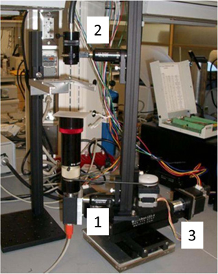
Figure 1. Tracking microscope. The sample of a worm crawling on an agar plate remains stationary while the imaging system moves to keep the worm in the center of view. The imaging system is built on a 2D translation stage driven by stepper motors (3). A CCD camera (Basler A601f) and lens (25mm focal length) images the worm from below (1) and a fiber light (Edmunds optics; model) illuminates it from above (2). A homemade stepper motor controller utilizing a SimpleStep controller board (SimpleStep; SSXYZ) controls the movement of the imaging system. A custom LabVIEW program (National Instruments, Austin, TX, USA) acquires and processes images of the worms, while simultaneously communicating with the motor controller to keep the worm in the center of the field.
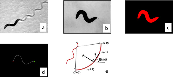
Figure 2. Image processing. (a) Worms move by changing their curvature in time and so we processed the worm images by parameterizing their center line. The images were made binary by thesholding the raw gray scale image (b), and individual worms were identified by filtering objects by size (c). The distance between the center of the mass of the worm and the center of the image was calculated and then the stage was moved the appropriate distances to re-center the worm. These correction distances were used to calculate the trajectory of the worm. The curvature of the worm perimeter was used to identify the tail (maximum curvature) and head (secondary maximum). (d) The images were then skeletonized to locate the center line. (e) The resulting curve was then then interpolated into 101 segments and the calculated angle between segments was used to parameterize the curve. Click here to view larger figure.
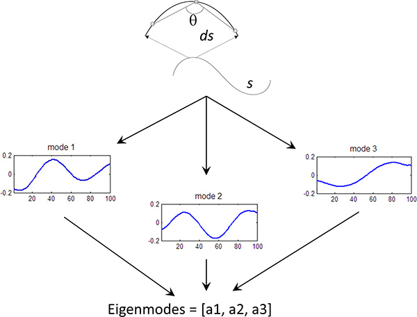
Figure 3. Eigenmode calculation. Fundamental curves of the worm shape have been calculated using Principle Component Analysis5. Each worm curve is represented by a linear sum of the eigenvectors (or eigenworms), where the amplitude of each components is known as the eigenmode (mode). We can quantify the behavior of the worm by measuring the first 3 eigenmodes of the worm shape over time.
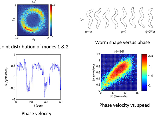
Figure 4. Phase and velocity. (a) The joint distribution of the first two modes for a limit cycle. (b) The phase or position on this limit cycle correlates with the phase of the worm’s undulatory position. (c) Using the phase velocity the worms forward and backward movements can be quantified. (d) The speed and direction along this limit cycles indicates the worm’s velocity. Click here to view larger figure.
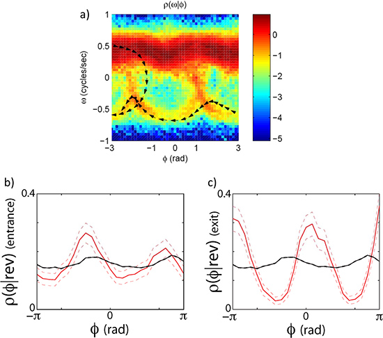
Figure 5. Phase dependent velocity switching. The transitions between forward and reverse states do not happen randomly along the oscillatory cycle. They (but still stochastically) happen at specific phases. (a) The joint distribution of the phase velocity and speed clearly indicates that worms leave and enter the forward state preferentially at specific phases. (b) shows a plot of the phase conditioned on the entrance to a reversal event. (c) shows the phase conditioned on the exit of a reversal event. The black line is the distribution of phase angles without conditioning on an exit or entrance.
Discussion
The study of locomotion and natural behavior requires non-invasive tracking techniques in partner with data reduction techniques. Here we have demonstrated an easy to use tracking system that records detailed images of C. elegans behavior as it crawls on the surface of an agar plate. The amount of information contained in these images is vast and high-dimensional, and so we have also developed methods to reduce the dimensionality of the data into only four fundamental measures. These measures are comprehensive and are easy to interpret with respect to worm behavior. For this work we show that worms transition between forward and backward states preferentially at different points in its undulatory cycle, a measure that is difficult to do by eye. This work is complementary to tracking systems that have been developed to measure behavior of worms at lower magnification8,9,10, and also to systems that are able to measure or modulate neuronal activity using genetically encoded reagents11,12.
While single organism tracking is a powerful method for quantification of behavior there are some limitations to the technique. The first is the fact that the system tracks only single organisms at a time. In comparison to fixed camera trackers which are able to track multiple organisms9,10, the throughput of our tracker is low. However, we are able to measure behavior of single organism for far longer periods of time than the multi-worm trackers, which is important for quantify long time scale behaviors such as hunger, egg-laying, and foraging. Also the tracker requires images which clearly identify the worm from the background. This precludes us from studying worm movements in environments that are visually cluttered or otherwise too complex for the image processing system to filter out the worm.
This system is flexible and can be used for other types of behavioral tracking. Instead of a homogenous environment, the worm can be tracked while submitted to spatial and temporal sensory information, similar to other tracking systems. For example, thermal stimulus can be applied via laser stimulus7,14, or chemical information can be applied via spatial gradients through the agar3. The system as a whole is flexible in design and can be used with other crawling systems such as Drosophila larvae.
Declarações
The authors have nothing to disclose.
Materials
| Name of the part | Company | Catalogue number | Comments (optional) |
| CCD camera | Basler | A601f | |
| Lens | Edmund Optics | MMS series | |
| Fiber Illumination | Dolan Jenner | DC-950H | |
| Translation stage | Deltron | LS3-4 | |
| Stepper Motor | US digital | MS23C | |
| Stepper motor drive | Gecko | G201 | |
| Stepper motor control | SimpleStep | SSXYZ | |
| All programming code is available. Please send a request email to the corresponding author. |
Referências
- Brenner, S. The genetics of Caenorhabditis elegans. Genética. 77 (1), 71-79 (1974).
- de Bono, M., Maricq, A. V. Neuronal substrates of complex behaviors in C. elegans. Annu. Rev. Neurosci. (28), 451-501 (2005).
- Pierce-Shimomura, J. T., Morse, T. M., Lockery, S. R. The fundamental role of pirouettes in Caenorhabditis elegans chemotaxis. J. Neurosci. 19 (21), 9557-9569 (1999).
- Gray, J. M., Hill, J. J., Bargmann, C. I. A circuit for navigation in Caenorhabditis elegans. Proc. Natl. Acad. Sci. U.S.A. 102 (9), 3184-3191 (2005).
- Baek, J. H., Cosman, P., Feng, Z., Silver, J., Schafer, W. R. Using machine vision to analyze and classify Caenorhabditis elegans behavioral phenotypes quantitatively. J. Neurosci. Methods. 118 (1), 9-21 (2002).
- Stephens, G. J., Johnson-Kerner, B., Bialek, W., Ryu, W. S. Dimensionality and Dynamics in the Behavior of C. elegans. PLoS Comput. Biol. 4 (1), e1000028 (2008).
- Stephens, G. J., Johnson-Kerner, B., Bialek, W., Ryu, W. S. From modes to movement in the behavior of C. elegans. PLoS One. 5 (11), e13914 (2010).
- Feng, Z., Cronin, C. J., Wittig, J. H., Sternberg, P. W., Schafer, W. R. An imaging system for standardized quantitative analysis of C. elegans behavior. BMC Bioinformatics. (5), 115 (2004).
- Ramot, D., Johnson, B. E., Berry, T. L., Carnell, L., Goodman, M. B. The Parallel Worm Tracker: A Platform for Measuring Average Speed and Drug-Induced Paralysis in Nematodes. PLoS One. 3 (5), e2208 (2008).
- Swierczek, N. A., Giles, A. C., Rankin, C. H., Kerr, R. A. High-throughput behavioral analysis in C. elegans. Nat. Methods. 8 (7), 592-598 (2011).
- Leifer, A. M., Fang-Yen, C., Gershow, M., Alkema, M. J., Samuel, A. D. Optogenetic manipulation of neural activity in freely moving Caenorhabditis elegans. Nat. Methods. 8 (2), 147-152 (2011).
- Stirman, J. N., Crane, M. M., Husson, S. J., Wabnig, S., Schultheis, C., Gottschalk, A., Lu, H. Real-time multimodal optical control of neurons and muscles in freely behaving Caenorhabditis elegans. Nat. Methods. 8 (2), 153-158 (2011).
- Ben Arous, J., Tanizawa, Y., Rabinowitch, I., Chatenay, D., Schafer, W. R. Automated imaging of neuronal activity in freely behaving Caenorhabditis elegans. J Neurosci Methods. 187 (2), 229-234 (2010).
- Wittenburg, N., Baumeister, R. Thermal avoidance in Caenorhabditis elegans: an approach to the study of nociception. Proc. Natl. Acad. Sci. U.S.A. 96 (18), 10477-10482 (1999).

