Dry Oxidation and Vacuum Annealing Treatments for Tuning the Wetting Properties of Carbon Nanotube Arrays
Summary
This article describes a simple method to fabricate vertically aligned carbon nanotube arrays by CVD and to subsequently tune their wetting properties by exposing them to vacuum annealing or dry oxidation treatment.
Abstract
In this article, we describe a simple method to reversibly tune the wetting properties of vertically aligned carbon nanotube (CNT) arrays. Here, CNT arrays are defined as densely packed multi-walled carbon nanotubes oriented perpendicular to the growth substrate as a result of a growth process by the standard thermal chemical vapor deposition (CVD) technique.1,2 These CNT arrays are then exposed to vacuum annealing treatment to make them more hydrophobic or to dry oxidation treatment to render them more hydrophilic. The hydrophobic CNT arrays can be turned hydrophilic by exposing them to dry oxidation treatment, while the hydrophilic CNT arrays can be turned hydrophobic by exposing them to vacuum annealing treatment. Using a combination of both treatments, CNT arrays can be repeatedly switched between hydrophilic and hydrophobic.2 Therefore, such combination show a very high potential in many industrial and consumer applications, including drug delivery system and high power density supercapacitors.3-5
The key to vary the wettability of CNT arrays is to control the surface concentration of oxygen adsorbates. Basically oxygen adsorbates can be introduced by exposing the CNT arrays to any oxidation treatment. Here we use dry oxidation treatments, such as oxygen plasma and UV/ozone, to functionalize the surface of CNT with oxygenated functional groups. These oxygenated functional groups allow hydrogen bond between the surface of CNT and water molecules to form, rendering the CNT hydrophilic. To turn them hydrophobic, adsorbed oxygen must be removed from the surface of CNT. Here we employ vacuum annealing treatment to induce oxygen desorption process. CNT arrays with extremely low surface concentration of oxygen adsorbates exhibit a superhydrophobic behavior.
Introduction
The introduction of synthetic materials with tunable wetting properties has enabled many applications including self-cleaning surfaces and hydrodynamic drag reduction devices.6,7 Many reported studies show that to successfully tune the wetting properties of a material, one have to be able to vary its surface chemistry and topographic surface roughness.8-11 Among many other available synthetic materials, nanostructured materials have attracted most of the attention due to their inherent multi-scaled surface roughness and their surfaces can be readily functionalized by common methods. Several examples of these nanostructured materials include ZnO,12,13 SiO2,12,14 ITO,12 and carbon nanotubes (CNT).15-17 We believe that the ability to reversibly tune the wetting properties of CNT has its own virtue since they are considered as one of the most promising materials for future applications.
CNT can be turned hydrophilic by functionalizing their surfaces with oxygenated functional groups, introduced during an oxidation treatment. To date, the most common method to introduce oxygen adsorbates to the CNT is the well-known wet oxidation techniques, involving the use of strong acids and oxidizing agents such as nitric acid and hydrogen peroxide.18-20 These wet oxidation techniques are difficult to be scaled up to industrial level because of safety and environmental issues and the considerable amount of time to complete the oxidation process. In addition, a critical point drying method may need to be employed to minimize the effect of capillary forces that may destroy the microscopic structure and overall alignment of the CNT array during the drying process. Dry oxidation treatments, such as UV/ozone and oxygen plasma treatments, offer a safer, faster, and more controlled oxidation process compared to the aforementioned wet oxidation treatments.
CNT can be made hydrophobic by removing the attached oxygenated functional groups from their surfaces. Thus far, complicated processes are always involved in producing highly hydrophobic CNT arrays. Typically, these arrays have to be coated with non-wetting chemicals, such as PTFE, ZnO, and fluoroalkylsilane,15,21,22 or be pacified by fluorine or hydrocarbon plasma treatment, such as CF4 and CH4.16,23 Although the abovementioned treatments are not too difficult to be scaled up to industrial level, they are not reversible. Once the CNT are exposed to these treatments, they can no longer be rendered hydrophilic by using common oxidation methods.
The methods presented herein show that the wettability of CNT arrays can be tuned straightforwardly and conveniently via a combination of dry oxidation and vacuum annealing treatments (Figure 1). Oxygen adsorption and desorption processes induced by these treatments are highly reversible because of their non-destructive nature and the absence of other impurities. Hence, these treatments allow CNT arrays to be repeatedly switched between hydrophilic and hydrophobic. Further, these treatments are very practical, economical, and can be easily scaled up since they can be performed using any commercial vacuum oven and UV/ozone or oxygen plasma cleaner.
Note that the vertically aligned CNT arrays used here are grown by the standard thermal chemical vapor deposition (CVD) technique. These arrays are typically grown on catalyst coated silicon wafer substrates in a quartz tube furnace under a flow of carbon containing precursor gasses at an elevated temperature. The average length of the arrays can be varied from a few micrometers to a millimeter long by changing the growth time.
Protocol
1. Carbon Nanotube (CNT) Array Growth
- Prepare a silicon wafer with at least one polished side. There is no specific requirement on the size, crystalline orientation, doping type, resistivity, and oxide layer thickness. We typically use a <100> n-type silicon wafer doped with phosphorous, with a diameter of 3 inch, a thickness of 381 μm, and a resistivity of 5-10 Ωcm. Usually this silicon wafer has a thermal oxide layer with a thickness of 300 nm.
- If the prepared silicon wafer does not have an oxide layer, add an oxide layer with a thickness of 300 nm on the polished side of the wafer. This oxide layer can be grown thermally or deposited by physical vapor deposition (PVD), preferably using e-beam evaporator.
- Deposit an aluminum oxide (Al2O3) buffer layer on the polished side of the wafer with an average thickness of 10 nm. Deposition using e-beam evaporator at an average deposition rate of 0.5 Å/sec is preferred. Use aluminum oxide pellets with purity of 99.99% or higher.
- Deposit an iron (Fe) catalyst layer on the polished side of the wafer with an average thickness of 1 nm. Since the uniformity of this buffer layer is extremely critical, deposition using e-beam evaporator at an average deposition rate of 0.3 Å/sec or less is preferred. Use iron pellets with purity of 99.95% or higher.
- Cut and dice the catalyst coated silicon wafer into multiple smaller chips, preferably into 1×1 cm samples.
- Load several catalyst coated silicon chips into a 1 inch diameter quartz tube furnace (Figure 2).
- Increase the temperature of the furnace to 750 °C under a constant flow of 400 sccm argon (Ar) gas at a pressure of 600 Torr.
- Once the growth temperature of 750 °C is reached, begin the pretreatment process by flowing a mixture of 200 sccm argon gas and 285 sccm hydrogen (H2) gas, while keeping the pressure constant at 600 Torr. Run the pretreatment process for 5 min.
- Once the pretreatment process is completed, begin the growth process by flowing a mixture of 210 sccm hydrogen gas and 490 sccm ethylene (C2H4) gas, while keeping the pressure constant at 600 Torr. Run the growth process for up to one hour while keeping the growth temperature constant at 750 °C. The length of the CNT arrays is determined by the growth time. CNT arrays with an average length of one millimeter can be achieved by growing them for one hour.2
- Bring the temperature of the furnace back to room temperature under a constant flow of 400 sccm argon gas at a pressure of 600 Torr. Unload the samples once the temperature of the furnace reaches room temperature.
- Characterize the overall growth characteristics, including growth quality, length, diameter, and packing density, by electron microscopy.
2. Oxygen Adsorption Induced by UV/Ozone Treatment
- Place several samples of CNT array under a high intensity mercury vapor lamp that generates UV radiation at a wavelength of 185 nm and 254 nm. These samples need to be placed at a distance of 5 – 20 cm from the lamp. A commercial UV/ozone cleaner can be used as an alternative (Figure 3).
- Expose these arrays to UV radiation in air at standard room temperature and pressure. The total exposure time depends on their physical properties, the power of UV radiation, and the degree of wettability that wants to be achieved. As an approximation, it takes about 30 min of UV irradiation at 100 mW/cm2 to completely switch a 15 μm tall CNT array from superhydrophobic to superhydrophilic.
- Measure the static contact angle of the UV/ozone treated CNT arrays for water using contact angle goniometer. Protocol to perform this measurement is described in section 5.
- Re-expose the CNT arrays to another round of UV/ozone treatment if they are not hydrophilic enough.
- Characterize the surface chemistry of the UV/ozone treated CNT array by x-ray photoelectron spectroscopy.
3. Oxygen Adsorption Induced by Oxygen Plasma Treatment
- Place several samples of CNT array in the chamber of an oxygen plasma cleaner/asher/etcher (Figure 4). A remote oxygen plasma cleaner/asher/etcher is preferable than the direct one because of its isotropic nature.
- Set the oxygen flow rate to 150 sccm and the chamber pressure to 500 mTorr. Set the RF power to 50 Watts.
- Expose these arrays to oxygen plasma for several minutes. The total exposure time depends on their physical properties and the degree of wettability that wants to be achieved. Care has to be taken because oxygen plasma is very capable of completely oxidizing the CNT into CO and CO2 molecules. As an approximation, it should take less than 30 min to completely switch a one millimeter tall CNT array from superhydrophobic to superhydrophilic.
- Measure the static contact angle of the oxygen plasma treated CNT arrays for water using contact angle goniometer. Protocol to perform this measurement is described in section 5.
- Re-expose the CNT arrays to another round of oxygen plasma treatment if they are not hydrophilic enough.
- Characterize the surface chemistry of the oxygen plasma treated CNT array by x-ray photoelectron spectroscopy.
4. Oxygen Desorption Induced by Vacuum Annealing Treatment
- Place several samples of CNT array in the chamber of a vacuum oven (Figure 5).
- Reduce the chamber pressure to at least 2.5 Torr.
- Increase the chamber temperature to 250 °C or higher.
- Expose these arrays to vacuum annealing treatment for several hours. The total exposure time depends on their physical properties and the degree of wettability that wants to be achieved. As an approximation, it takes at least 3 hr to completely switch a 15 μm tall CNT array from superhydrophilic to superhydrophobic and more than 24 hr to convert a one millimeter tall CNT array from superhydrophilic to superhydrophobic.
- Measure the static contact angle of the vacuum annealed CNT arrays for water using contact angle goniometer. Protocol to perform this measurement is described in section 5.
- Re-expose the arrays to another round of vacuum annealing treatment if they are not hydrophobic enough.
- Characterize the surface chemistry of the vacuum annealed CNT array by x-ray photoelectron spectroscopy.
5. Wetting Properties Characterization
- Prepare a contact angle goniometer. Fill the microsyringe assembly with deionized water. This syringe has to be equipped with a 22 gauge flat-tipped straight needle or a smaller needle. Turn on the illuminator.
- Place a sample of CNT array on the contact angle goniometer sample table. Make sure this sample is not tilted toward one direction.
- Bring the microneedles assembly closer to the sample and slowly dispense a 5 μl water droplet on top surface of the CNT array.
- Capture a picture of the water droplet once it has come to rest on the top surface of the CNT array. Make sure an equilibrium condition has been achieved before taking the image.
- Calculate the contact angle by processing the captured image with a dedicated software such as DROPimage by ramé-hart or LBADSA.24
Representative Results
The CVD method described above results in densely packed vertically aligned multi-walled CNT arrays with a typical diameter, number of wall, and inter-nanotube spacing of about 12 – 20 nm, 8 – 16 walls, and 40 – 100 nm respectively. The average length of the arrays can be varied from a few micrometers long (Figure 6a) to a millimeter long (Figure 6b) by changing the growth time from 5 min to 1 hr respectively. Typically the vertical alignment is good at larger length scale and some entanglements present at smaller length scale.1
After being exposed to UV/ozone or oxygen plasma treatment, the CNT arrays become hydrophilic and they can be wetted by water. A prolonged exposure to these treatments turns the CNT arrays superhydrophilic, indicated by their extremely low static contact angle of less than 30 °. Since these superhydrophilic CNT arrays can be wetted very easily by water, they show their original black color whenever they are being completely submerged in water (Figure 7).
After being exposed to vacuum annealing treatment, the CNT arrays become hydrophobic and they cannot be easily wetted by water. A prolonged exposure to this treatment turns the CNT arrays superhydrophobic, indicated by their extremely high static contact angle of more than 150 °. Since these superhydrophobic CNT arrays repel water very strongly, they appear reflective whenever they are being completely submerged in water due to the presence of thin air films on their surfaces (Figure 7).
A simple oxidation-time-independent relation can be observed from a plot of oxygen-to-carbon atomic ratio (O/C ratio) of the CNT arrays to their static contact angle. The O/C ratio, corresponds to the degree of oxidation of the CNT array, can be calculated from the O 1s and C 1s peaks obtained by x-ray photoelectron spectroscopy (XPS). The O/C ratio decreases as the static contact angle of the array increases, where the O/C ratio of superhydrophilic CNT arrays is higher than 15% and that of superhydrophobic CNT arrays is lower than 8% (Figure 8a). Notice that the O/C ratio of superhydrophobic CNT arrays is not zero, suggesting that a small amount of oxygen cannot be easily removed by vacuum annealing treatment.
Deconvolution of the high resolution XPS spectra at the binding energy of 283-293 eV shows four distinct peaks, with one primary peak associated with the presence of sp2 C-C 1s bonds (~284.9 eV) and three secondary peaks associated with the presence of hydroxyl C-OH (~285.4 eV), carbonyl C=O (~287.4 eV), and carboxyl -COOH (~289.7 eV) functional groups.20,25 As the CNT arrays undergo a dry oxidation treatment, they become more hydrophilic, and all peaks associated with C-OH, C=O and -COOH groups become more pronounced (Figure 8b). At a longer exposure time, the surface concentration of C=O groups decreases slightly while that of C-OH and -COOH groups continues to increase (Figure 8c). On the other hand, the amount of C-OH, C=O and -COOH groups decreases after the vacuum annealing treatment (Figure 8d). The existence of these peaks suggests that the vacuum annealing treatment does not completely remove oxygen adsorbates from the CNT arrays, even though these arrays are found to be superhydrophobic.
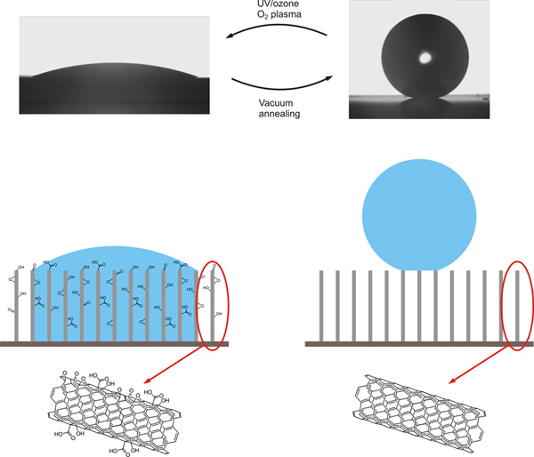
Figure 1. Wetting properties of CNT arrays can be varied via a combination of UV/ozone or oxygen plasma treatment and vacuum annealing treatment. Oxygen adsorption occurs during the UV/ozone or oxygen plasma treatment while oxygen desorption occurs during vacuum annealing treatment. CNT arrays become more hydrophilic after being exposed to UV/ozone or oxygen plasma treatment and more hydrophobic after being exposed to vacuum annealing treatment. Click here to view larger figure.
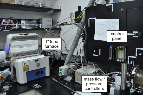
Figure 2. A 1 inch diameter quartz tube furnace, equipped with digital mass flow and pressure controllers, for CNT array growth.
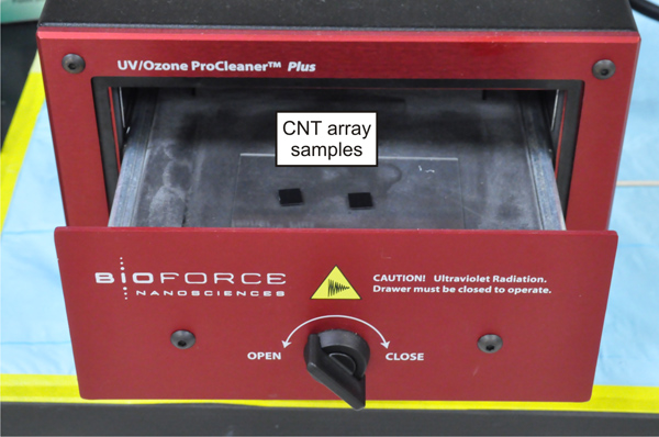
Figure 3. A commercial UV/ozone cleaner used to render CNT arrays hydrophilic by functionalizing them with oxygenated functional groups.
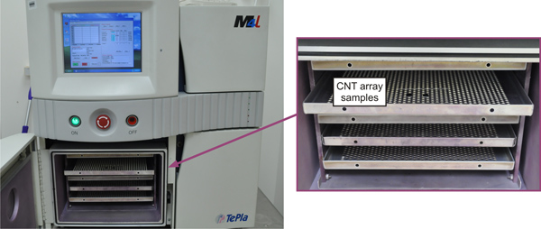
Figure 4. A commercial oxygen plasma cleaner used to render CNT arrays hydrophilic by functionalizing them with oxygenated functional groups.
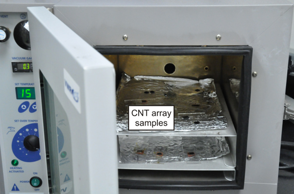
Figure 5. A commercial vacuum oven used for introducing oxygen desorption process on the CNT array so that they become more hydrophobic.

Figure 6. Low magnification SEM images of CNT array with an average length of 15 μm (a) and 985 μm (b).

Figure 7. An image of two CNT arrays with opposite wetting properties fully submerged in water. The highly hydrophilic UV/ozone treated CNT array (§) shows its original black color while the superhydrophobic vacuum annealed CNT array (‡) appears reflective due to the presence of a thin air film on its surface.
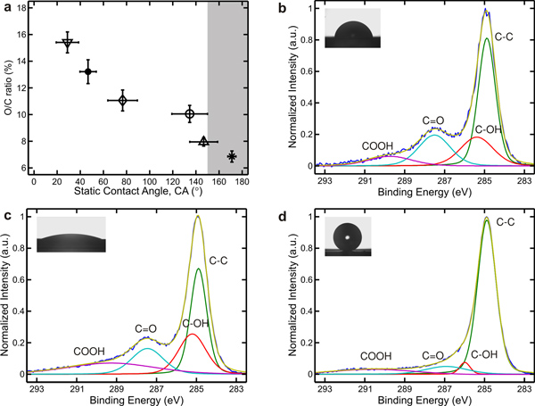
Figure 8. A plot of oxygen to carbon atomic ratio (O/C ratio) of CNT arrays as a function of static contact angle for water, with shaded region indicates the superhydrophobic regime (a). The O/C ratio can is calculated from the O 1s and C 1s peaks obtained by XPS. Deconvolution of high resolution XPS spectra of the C 1s peak of a mildly hydrophilic CNT array (b), a highly hydrophilic CNT array (c), and a superhydrophobic CNT array (d).
Discussion
We consider UV/ozone treatment as the most convenient oxidation technique because it can be performed in air at a standard room temperature and pressure for up to several hours, depending on the length of the CNT array and the power of the UV radiation. UV radiation, generated by a high intensity mercury vapor lamp at 185 nm and 254 nm, breaks the molecular bonds on the outer wall of CNT allowing ozone, converted simultaneously from air by UV radiation, to oxidize their surface.26,27 The oxidation process stops once the CNT surfaces are fully functionalized, preventing the CNT to be completely oxidized into CO and CO2 molecules.
In contrast, oxygen plasma treatment has to be performed in a special chamber at a reduced pressure and a constant oxygen flow rate. Typically, oxygen plasma is generated remotely under 50 Watts of RF power and delivered at a constant flow rate of 150 SCCM and a chamber pressure of 500 mTorr for several minutes. Although oxygen plasma treatment allows a much faster oxidation process, care has to be taken because it is very capable of completely oxidizing the CNT into CO and CO2 molecules. .
UV/ozone and oxygen plasma treatments have been successfully employed to functionalize the surface of CNT with oxygenated functional groups.26-31 However, none of these published methods have been previously performed on CNT arrays. Although the oxidation method described herein is similar to these published methods, it is optimized for CNT arrays, not CNT powders. This current method utilizes low UV lamp irradiation power and plasma generator power to keep the oxygen adsorption rate low. Such low oxygen adsorption rate is essential to ensure that the functionalization process occurs uniformly across the CNT array sample without damaging them. Therefore, the oxidation time for CNT arrays is typically longer than that for CNT powders.
Vacuum annealing treatment is employed to induce oxygen desorption process without using any harsh reducing agents. Vacuum annealing treatment performed at a mild vacuum of about 2.5 Torr and a moderate temperature of about 250 °C for several hours is found to be sufficient to deoxidize CNT arrays.
The surface hydrophilicity of UV/ozone and oxygen plasma treated CNT arrays is found to be stable in air at standard room temperature for more than 2 months. On the other hand, the surface hydrophobicity of vacuum annealed CNT arrays is found to be stable in air at standard room temperature for only 3 weeks. These vacuum annealed CNT arrays are gradually losing their hydrophobicity until they become mildly hydrophilic. However, the superhydrophobic CNT arrays produced by vacuum annealing treatment are found to remain superhydrophobic for more than 2 months storage in air at standard room temperature.
Here we have shown that the wettability of CNT arrays can be tuned via a combination of dry oxidation and vacuum annealing treatments. However, these treatments have one main limitation. Both dry oxidation and vacuum annealing treatments perform poorly on low quality CNT arrays. In general, low quality CNT arrays are defined as ones with a high amount of metal contaminants or amorphous carbon coatings. The oxide layers on the metal contaminants inhibit further oxygen adsorption, rendering the oxidation process to functionalize CNT without damaging their structure unfeasible. In addition, these oxide layers are inherently hydrophilic and can only be removed by an exposure to a reducing agent, not by vacuum annealing treatment. Similarly, lack of dangling bonds on amorphous carbon coatings makes them naturally hydrophilic, such that they cannot be turned hydrophobic just by vacuum annealing treatment. Therefore, these low quality CNT arrays are extremely difficult to be turned hydrophobic by vacuum annealing treatment.
Divulgaciones
The authors have nothing to disclose.
Acknowledgements
This work was supported by The Charyk Foundation and The Fletcher Jones Foundation under grant number 9900600. The authors gratefully acknowledge the Kavli Nanoscience Institute at the California Institute of Technology for use of the nanofabrication instruments, the Molecular Materials Research Center of the Beckman Institute at the California Institute of Technology for use of the XPS and contact angle goniometer, and the Division of Geological and Planetary Sciences of the California Institute of Technology for use of SEM.
Materials
| Material Name | Company | Catalogue Number | Comments (optional) |
| Lindberg Blue M Mini-Mite tube furnace | Thermo Scientific | TF55030A | 1″ tube furnace for CNT array growth |
| Electronic mass flow controllers | MKS | PFC-50 πMFC | Max flow rate of 1000 sccm |
| Electronic pressure controller | MKS | PC-90 πPC | Max pressure of 1000 Torr |
| 1″ quartz tube | MTI Corp. | >EQ-QZTube-25GE-610 | 1″ D x 24″ L |
| Hydrogen gas | Airgas | HY UHP200 | CNT array growth precursor gas, 99.999% purity |
| Ethylene gas | Matheson | G2250101 | CNT array growth precursor gas, 99.999% purity |
| Argon gas | Airgas | AR UHP200 | CNT array growth precursor gas, 99.999% purity |
| Silicon wafer | El-Cat | 2449 | With 300 nm polished thermal oxide layer |
| Iron pellets | Kurt J Lesker | EVMFE35EXEA | 99.95% purity |
| Aluminum oxide pellets | Kurt J Lesker | EVMALO-1220B | 99.99% purity |
| E-beam evaporator | CHA Industries | CHA Mark 40 | For buffer and catalyst layer deposition |
| UV/ozone cleaner | BioForce Nanosciences | ProCleaner Plus | For oxidizing CNT array |
| Oxygen plasma cleaner | PVA TePla | M4L | For oxidizing CNT array |
| Vacuum oven | VWR | 97027-664 | For deoxidizing CNT array |
| SEM | Zeiss | 1550 VP | For CNT array growth characterization |
| XPS | Surface Science | M-Probe | For surface chemistry characterization |
| Contact angle goniometer | ramé-hart | Model 190 | For wetting properties characterization |
Referencias
- Sansom, E., Rinderknecht, D., Gharib, M. Controlled partial embedding of carbon nanotubes within flexible transparent layers. Nanotechnology. 19, 035302 (2008).
- Aria, A. I., Gharib, M. Reversible Tuning of the Wettability of Carbon Nanotube Arrays: The Effect of Ultraviolet/Ozone and Vacuum Pyrolysis Treatments. Langmuir. 27, 9005-9011 (2011).
- Lee, S. W., et al. High-power lithium batteries from functionalized carbon-nanotube electrodes. Nat. Nano. 5, 531-537 (2010).
- Aria, A. I., Gharib, M. Effect of Dry Oxidation on the Performance of Carbon Nanotube Arrays Electrochemical Capacitors. MRS Proceedings. 1407, (2012).
- Bianco, A., Kostarelos, K., Prato, M. Applications of carbon nanotubes in drug delivery. Current Opinion in Chemical Biology. 9, 674-679 (2005).
- Scardino, A. J., Zhang, H., Cookson, D. J., Lamb, R. N., Nys, R. d. The role of nano-roughness in antifouling. Biofouling: The Journal of Bioadhesion and Biofilm Research. 25, 757-767 (2009).
- Rothstein, J. Slip on Superhydrophobic Surfaces. Annual Review of Fluid Mechanics. 42, 89-109 (2010).
- Emsley, J. Very strong hydrogen-bonding. Chemical Society Reviews. 9, 91-124 (1980).
- Bhushan, B., Jung, Y., Koch, K. Micro- nano- and hierarchical structures for superhydrophobicity, self-cleaning and low adhesion. Philosophical Transactions – Royal Society. Mathematical, Physical and Engineering Sciences. 367, 1631-1672 (2009).
- Krupenkin, T., Taylor, J., Schneider, T., Yang, S. From rolling ball to complete wetting: The dynamic tuning of liquids on nanostructured surfaces. Langmuir. 20, 3824-3827 (2004).
- Sun, T., et al. Control over the Wettability of an Aligned Carbon Nanotube Film. Journal of the American Chemical Society. 125, 14996-14997 (2003).
- Ebert, D., Bhushan, B. Transparent, Superhydrophobic, and Wear-Resistant Coatings on Glass and Polymer Substrates Using SiO2, ZnO, and ITO Nanoparticles. Langmuir. 28, 11391-11399 (2012).
- Feng, X., et al. Reversible Super-hydrophobicity to Super-hydrophilicity Transition of Aligned ZnO Nanorod Films. Journal of the American Chemical Society. 126, 62-63 (2003).
- Xu, L., Karunakaran, R. G., Guo, J., Yang, S. Transparent, Superhydrophobic Surfaces from One-Step Spin Coating of Hydrophobic Nanoparticles. ACS Appl. Mater. Interfaces. 4, 1118 (2012).
- Lau, K., et al. Superhydrophobic carbon nanotube forests. Nano Letters. 3, 1701-1705 (2003).
- Hong, Y., Uhm, H. Superhydrophobicity of a material made from multiwalled carbon nanotubes. Applied Physics Letters. 88, 244101 (2006).
- Lee, C. H., Johnson, N., Drelich, J., Yap, Y. K. The performance of superhydrophobic and superoleophilic carbon nanotube meshes in water-oil filtration. Carbon. 49, 669-676 (2011).
- Hummers, W. S., Offeman, R. E. Preparation of Graphitic Oxide. Journal of the American Chemical Society. 80, 1339 (1958).
- Park, S., Ruoff, R. Chemical methods for the production of graphenes. Nature Nanotechnology. 4, 217-224 (2009).
- Peng, Y., Liu, H. Effects of Oxidation by Hydrogen Peroxide on the Structures of Multiwalled Carbon Nanotubes. Industrial & Engineering Chemistry Research. 45, 6483-6488 (2006).
- Huang, L., et al. Stable superhydrophobic surface via carbon nanotubes coated with a ZnO thin film. The Journal of Physical Chemistry. B. 109, 7746-7748 (2005).
- Feng, L., et al. Super-Hydrophobic Surfaces: From Natural to Artificial. Advanced Materials. 14, 1857-1860 (2002).
- Cho, S., Hong, Y., Uhm, H. Hydrophobic coating of carbon nanotubes by CH4 glow plasma at low pressure, and their resulting wettability. Journal of Materials Chemistry. 17, 232-237 (2007).
- Stalder, A., Kulik, G., Sage, D., Barbieri, L., Hoffmann, P. A snake-based approach to accurate determination of both contact points and contact angles. Colloids and Surfaces. A, Physicochemical and Engineering Aspects. , 286-2892 (2006).
- Naseh, M. V., et al. Fast and clean functionalization of carbon nanotubes by dielectric barrier discharge plasma in air compared to acid treatment. Carbon. 48, 1369-1379 (2010).
- Mawhinney, D. Infrared spectral evidence for the etching of carbon nanotubes: Ozone oxidation at 298 K. Journal of the American Chemical Society. 122, 2383-2384 (2000).
- Sham, M., Kim, J. Surface functionalities of multi-wall carbon nanotubes after UV/Ozone and TETA treatments. Carbon. 44, 768-777 (2006).
- Banerjee, S., Wong, S. Rational sidewall functionalization and purification of single-walled carbon nanotubes by solution-phase ozonolysis. The Journal of Physical Chemistry. B. 106, 12144-12151 (2002).
- Xu, T., Yang, J., Liu, J., Fu, Q. Surface modification of multi-walled carbon nanotubes by O2 plasma. Applied Surface Science. 253, 8945-8951 (2007).
- Felten, A., Bittencourt, C., Pireaux, J. J., Van Lier, G., Charlier, J. C. Radio-frequency plasma functionalization of carbon nanotubes surface O2, NH3, and CF4 treatments. Journal of Applied Physics. 98, 074308 (2005).
- Chen, C., Liang, B., Ogino, A., Wang, X., Nagatsu, M. Oxygen Functionalization of Multiwall Carbon Nanotubes by Microwave-Excited Surface-Wave Plasma Treatment. The Journal of Physical Chemistry C. 113, 7659-7665 (2009).

