In Vitro Ovule Cultivation for Live-cell Imaging of Zygote Polarization and Embryo Patterning in Arabidopsis thaliana
Özet
This manuscript describes an in vitro ovule cultivation method that enables live-cell imaging of Arabidopsis zygotes and embryos. This method is utilized to visualize the intracellular dynamics during zygote polarization and the cell fate specification in developing embryos.
Abstract
In most flowering plants, the zygote and embryo are hidden deep in the mother tissue, and thus it has long been a mystery of how they develop dynamically; for example, how the zygote polarizes to establish the body axis and how the embryo specifies various cell fates during organ formation. This manuscript describes an in vitro ovule culture method to perform live-cell imaging of developing zygotes and embryos of Arabidopsis thaliana. The optimized cultivation medium allows zygotes or early embryos to grow into fertile plants. By combining it with a poly(dimethylsiloxane) (PDMS) micropillar array device, the ovule is held in the liquid medium in the same position. This fixation is crucial to observe the same ovule under a microscope for several days from the zygotic division to the late embryo stage. The resulting live-cell imaging can be used to monitor the real-time dynamics of zygote polarization, such as nuclear migration and cytoskeleton rearrangement, and also the cell division timing and cell fate specification during embryo patterning. Furthermore, this ovule cultivation system can be combined with inhibitor treatments to analyze the effects of various factors on embryo development, and with optical manipulations such as laser disruption to examine the role of cell-cell communication.
Introduction
The basic body plan of an organism develops from a unicellular zygote. In most flowering plants, zygotic division generates an apical and a basal cell, which develop into the shoot and root, respectively1. Therefore, it is important to understand how the plant body is formed during embryogenesis, but there has not been an effective tool to directly observe the dynamics of living zygotes and embryos because they develop deep in the flower. In several monocot species, such as maize and rice, an in vitro fertilization method has been established2,3. In this method, isolated sperm and egg cells are fused electrically or chemically, and the generated cell can develop into a fertile plant. However, in dicot plants, there is no in vitro fertilization method that can produce proper embryos, presumably because of the non-synchronized cell cycle state of male and female gametes4,5. In addition, the embryo-surrounding tissue (endosperm) plays important roles in embryo development6.
In a model dicot species, A. thaliana, an in vitro cultivation method was developed by focusing on the whole ovule, which contains both the embryo and endosperm7. This system was successfully used to analyze the effects of various chemical reagents on embryogenesis, but it is not suitable for time-lapse imaging because it has a low survival rate. Therefore, a novel in vitro ovule cultivation system was developed in order to start as early as the zygote stage and produce fertile plants at a high ratio8. After various trials, it was found that Nitsch medium and trehalose significantly improved the survival rate of ovules8. In addition, because the ovule expands as it grows and thus frequently moves away from the observation field of the microscope, a PDMS device was developed to fix the ovule in the medium9. The PDMS device enabled the long-term imaging for 3 – 4 days, which is sufficient to trace the development from a zygote to a heart-stage embryo. Using this method, it becomes possible to visualize the dynamics of zygote polarization and embryo patterning, not only under normal conditions, but also in the presence of chemical inhibitors or in various mutant backgrounds8,10,11.

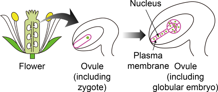
Figure 1: Schematic Diagram of the Specific Fluorescent Markers used to Visualize Zygotes and Embryos Through the Ovule.
The Arabidopsis zygote develops into an embryo in the ovule, which is generated deep inside the flower. In this in vitro cultivation system, the zygote and embryo are observed through the ovule, and thus it is important to use specific fluorescent markers that are not expressed in other ovule tissues. Please click here to view a larger version of this figure.
Protocol
1. Preparation of the In Vitro Ovule Culture Medium
- Make the liquid medium forthe in vitro ovule culture ("N5T medium") containing 1x Nitsch basal salt mixture, 5% (w/v) trehalose dihydrate, 0.05% (w/v) 2-(N-morpholino)ethanesulfonic acid (MES)-KOH (pH 5.8), and 1x Gamborg's vitamin solution.
- Adjust the pH to 5.8 with KOH.
- Sterilize the medium by autoclaving it (121 °C, 20 min) or filtering it through a 0.22-µm filter.
NOTE: The sterilized medium can be stored at 4 °C for 2 – 3 months.
2. Preparation of the PDMS Micropillar Array Device
- Cut the PDMS micropillar device by a knife, razor blade or scissors to fit into the glass part (14 mm φ) of a 35 mm glass-bottom dish.
NOTE: The full procedure of the PDMS device construction is described in previous papers8,9, and thus the details are omitted here. Glass-bottom dishes with smaller volumes, such as 4-well or 96-well plates, can be used for short-term imaging without the device. - Sterilize the upper side of the PDMS device under UV light for 15 min.
- Turn the PDMS device over by using square tip tweezers, and keep it under UV light for 15 min to sterilize the bottom.
- Transfer the sterilized PDMS device into a 35 mm culture dish and add the N5T medium until the device is completely soaked in the medium (approximately 5 – 7 mL).
- Put the dish into a vacuum chamber, and reduce the pressure to degas. Keep vacuuming for 3 h to overnight until the air in the device is replaced by medium.
NOTE: The device can be detached by air bubbles under a strong vacuum. - Take the device from the dish by holding it with square tip tweezers and put it on a paper towel to remove the extra medium on the side and bottom.
NOTE:The medium on the micropillar array (upper surface) should not be removed because this will be used for the ovule cultivation. - Transfer the device onto a 76 mm x 26 mm slide glass, ensuring to keep the micropillar part as the upper side, and cover the device with 35 mm culture dish lid to prevent the medium from drying out during the following ovule extraction.
3. Silique Dissection and Ovule Extraction
- Sterilize a needle (0.40 mm G) and fine tweezers by wiping with 70% ethanol. The needle is easily handled by attaching it to a syringe or wood stick.
- Check the inflorescence of the plant, and select the proper siliques for the experiment. The approximately 5 mm siliques contain zygotes, and the 8 – 10 mm siliques include young globular embryos.
- Excise the siliques by using tweezers, and place them on double-sided tape on a 76 x 26 mm slide glass. One silique contains about 40 – 60 ovules, and 3 – 4 siliques (i.e., 120 – 240 ovules) are sufficient for one device.
- Open the silique (ovary wall) to see the ovules inside using the sterilized needle and tweezers under a stereomicroscope. Cut only the ovary wall so that the ovules are not damaged.
- Transfer the opened silique into the N5T medium on the PDMS device (prepared in step 2.7), and release the ovules into the medium with the needle or tweezers.
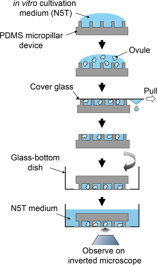
- Put a small cover glass (18 mm x 18 mm) onto the PDMS device to push the ovules into the spaces in the micropillar array.
- Take the cover glass off by pulling it horizontally using tweezers or fingers to remove extra medium.
- Turn the PDMS device upside down, place it into a 35 mm glass-bottom dish, and slightly press the device by pushing using the square tip tweezers to stick it to the glass.
- Pour N5T medium gently into the glass-bottom dish by decanting the medium bottle until the PDMS device is completely soaked in the medium, and seal the dish with paraffin film.
NOTE: The PDMS device can be recycled, but devices that are too old are easily detached from the glass bottom. Additionally, the device may float if it is not completely degassed in step 2.5 or the medium is poured too quickly.

Figure 2: Schematic Procedure for Sample Preparation.
This schematic flow corresponds to steps 3.5 to 4.1. Please click here to view a larger version of this figure.
4. Time-lapse Imaging
- Place the glass-bottom dish that was prepared in step 3.9 on an inverted microscope, and select suitable ovules to focus on.
NOTE: Because the ovules vary in stage, position, and direction, suitable ovules should be found by checking their marker fluorescence. - Start the live-imaging according tothe manufacturer's instructions of the microscope system.
NOTE: The microscope equipment and parameters are diverse, and thus the users should choose the proper settings that fit to the experiment purpose. As an example, the settings used in this manuscript are listed in Table 1.
| Equipment/setting | Figure 3 (A) and Supplemental Videos 1 and 4 | Figure 3 (B) and Supplemental Video 2 | Supplemental Video 3 |
| Microscope | laser-scanning inverted microscope (A1R MP) | spinning-disk confocal inverted microscope (CSU-W1) | box-type inverted confocal microscope system with a stable incubation chamber (CV1000) |
| Laser | Ti:sapphire femtosecond pulse laser | 488-nm and 561-nm LD lasers | 488-nm and 561-nm LD laser |
| Objective lens | 40X water-immersion objective lens (NA = 1.15) with immersion medium | 60X silicone oil immersion objective lens (NA = 1.30), mounted on a Piezo focus drive | 40X objective lens (NA = 0.95) |
| Detector | external non-descanned GaAsP PMT detector | EMCCD camera | EMCCD camera |
| Dichroic mirror | DM495 and DM560 | DM488/561 | DM400-410/488/561 |
| Filter | band-pass filters; 534/30 nm and 578/105 nm | band-pass filters; 520/35 nm, and 593/46 nm | band-pass filters; 520/50 nm and 617/73 nm |
| Slice along z-axis | 31 z-stacks with 1-µm intervals | 17 z-stacks with 3-µm intervals | 7 z-stacks with 5-µm intervals |
| Time interval | 20 min | 5 min | 10 min |
Table 1: The Microscope Systems and Settings Used in This Manuscript.
The microscopes and parameters are diverse, and thus each user should choose the suitable system for the experiment.
- Check the acquired image sequence, and convert it to the general movie format, such as .avi or .mov for presentation.
NOTE: If the microscope software cannot output the images as a movie format, it is possible to save the images as .tif and then open them in ImageJ, an open source program inspired by NIH Image, to change the file type. ImageJ is provided at: https://imagej.nih.gov/ij/. ImageJ can also be used to make a Z-stuck movie, such as the maximum-intensity projection, as described at: https://imagej.net/Z-functions.
Representative Results
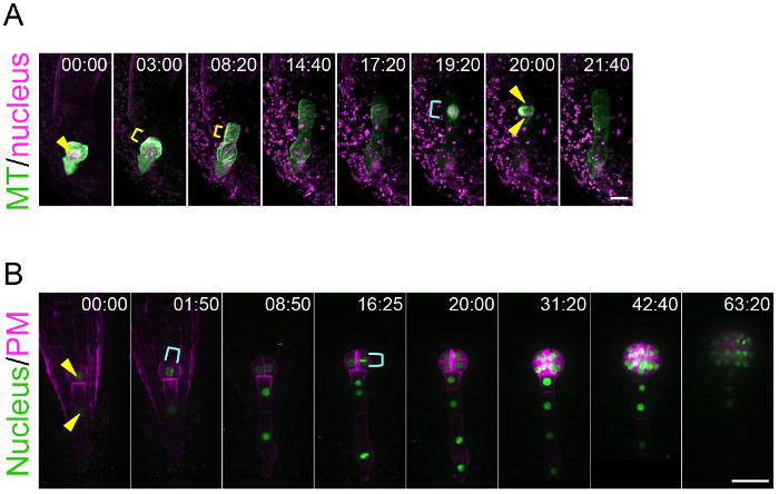
By using this ovule cultivation system, this method can trace the living dynamics of zygote polarization and embryo patterning. This is an achievement because previously there was no technique to visualize the real-time behavior of the zygote and embryo, which are hidden deep in the mother tissue. Figure 3A and Supplemental Video 1 show that the microtubules (MTs) in the young zygote accumulate as a transverse ring in the subapical region10. This MT ring is maintained while the zygote elongates in the apical direction. After the completion of zygote elongation and nuclear migration to the apical region, the MT ring disappears and the MTs form a spindle to separate the DNA. Figure 3B and Supplemental Video 2 show that embryonic cells coordinately divide to form a radially symmetrical globular shape8. This method is applicable for pharmacological experiments. For example, after the application of an actin polymerization inhibitor (latrunculin B; Lat B) into the liquid medium culturing the zygote-containing ovules, the polar nuclear migration was inhibited and thus the zygote divided in a more symmetric manner, indicating the role of actin filament on the zygote polarization (Supplemental Video 3)10. Long-term imaging of embryo development enables the tracing of the direction and timing of individual cell divisions, meaning that the geometry and cell cycle duration can be statistically analyzed. Indeed, we previously showed that the cell division of the apical cell lineage is faster than that of the basal cell region8.

Figure 3: Live-imaging of Zygote Polarization and Embryo Patterning.
(A) Time-lapse observation of a zygote expressing specific markers for the nucleus (histone 2B-tdTomato; magenta) and microtubules (MTs, Clover-TUA6; green). The images were acquired using a laser-scanning inverted microscope (A1R MP). (B) Time-lapse observation of an embryo expressing markers for the nucleus (histone 2B-sGFP; green) and plasma membrane (PM, tdTomato-LTI6b; magenta). The images were acquired using a spinning-disk confocal inverted microscope (CSU-W1). The images were shown as maximum-intensity projection images, and the numbers indicate the time (h:min) from the first frame. Arrowheads and yellow brackets show the nucleus and the transverse MT ring, respectively. Cyan brackets indicate the spindle (A) and dividing nucleus (B). Scale bars: 10 µm (A) and 30 µm (B). Please click here to view a larger version of this figure.
Discussion
This manuscript introduces a simple in vitro ovule cultivation protocol that is efficient for use in the live-cell imaging of developing zygotes and embryos.
The design of the PDMS device may need optimization according to the embryo stage. The first developed device was a microcage array to adjust the orientation and to fix the position of the ovules9, and then a micropillar device was constructed to trap ovules more efficiently8. Furthermore, the micropillars are thinner and softer than a microcage, and thus do not prevent ovule expansion during long-term observation. This micropillar device can hold an ovule for several days, from the zygotic stage until the embryonic heart stage8. Ultimately, however, the height of the fully expanded ovule exceeds the micropillar height, and thus it pushes the device away. Therefore, the height and spacing of the micropillars should be adjusted if later-stage embryos are the focus.
Because the ovule is positioned at the bottom of the dish, an inverted microscope must be used. A confocal microscope is sufficient to monitor the cell division pattern as shown in Figure 3B and Supplemental Videos 2 and 38,11, and a spinning-disk confocal microscope is important to perform long-term imaging without cell damage. In contrast, a two-photon excitation microscopy, which is suitable for deep imaging of living organisms12, is necessary to visualize the intracellular dynamics of the zygote (Figure 3A and Supplemental Video 1)10. Therefore, it is crucial to use the suitable microscope system for the experiments.
As described in the Introduction and Representative Results, there were no existing methods that can monitor the living dynamics of the zygote and embryo developing in the ovule. Therefore, by using this ovule cultivation method, the details of zygote polarization and embryo patterning have been clarified for the first time.
This method is applicable for pharmacological experiments as shown in Supplemental Video 3. Moreover, this imaging system was used to evaluate the effects of newly synthesized compounds on embryonic cell division11. It was also successfully combined with laser disruption, and thus revealed that when the apical cell is harmed, the basal cell derivatives change their cell fate to produce a new apical cell8. Therefore, further application of this method to various materials and techniques will provide powerful tools to understand the molecular mechanisms of embryogenesis.
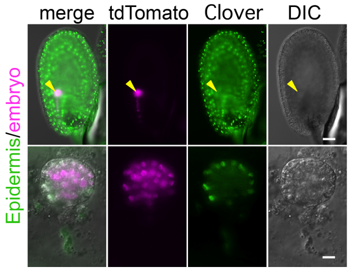
To perform long-term imaging with this method, the crucial step is to prepare a specific and bright fluorescent marker that labels the target tissues and/or structures. Because the zygote and embryo are observed through the ovule as shown in Figure 1, background signals in the endosperm and other ovule tissues can mask the true signal in the embryo (Figure 4). In addition, to detect a weak signal, the laser power of the microscope needs to be increased, but this can harm the ovule during long-term observation. Supplemental Video 4 shows that the high laser power increased auto-fluorescence in the ovule, and finally shrunk the embryo sac, in which the zygote was crushed. Therefore, a specific and bright marker line should be established before starting the experiment. With respect to higher brightness, tdTomato and Clover are better than RFP and GFP, respectively.

Figure 4: Background Fluorescent Signal in Ovule Masks Embryonic Signal.
Image of the ovule expressing the markers of the embryonic nucleus (histone 2B-tdTomato; magenta) and the epidermal nucleus (histone 2B-Clover; green). Whole ovule and excised embryo are shown in the upper and lower panels, respectively. Arrows point to the position of the embryo. The histone 2B-Clover is expressed not only in embryo, but also in the entire ovule, and thus it is difficult to find the embryonic signal through the ovule. Scale bars: 50 µm (A) and 10 µm (B). Please click here to view a larger version of this figure.
Açıklamalar
The authors have nothing to disclose.
Acknowledgements
Microscopy in this work was conducted at the Institute of Transformative Bio-Molecules (WPI-ITbM) of Nagoya University and supported by the Japan Advanced Plant Science Network. This work was supported by grants from the Japan Science and Technology Agency (ERATO project to T.H. and M.U.) and from the Japan Society for the Promotion of Science: a Grant-in-Aid for Scientific Research on Innovative Areas (Nos. JP24113514, JP26113710, JP15H05962, and JP15H05955 for M.U., and Nos. JP16H06465, JP16H06464 and JP16K21727 for T.H), a Grant-in-Aid for Young Scientists (B, Nos. JP24770045 and JP26840093 for M.U.), and a Grant-in-Aid for challenging Exploratory Research (No. JP16K14753 for M.U.).
Materials
| Nitsch basal salt mixture | Duchefa | N0223 | |
| trehalose dihydrate | Wako Pure Chemical | 206-18455 | |
| MES | Dojindo | 345-01625 | |
| Gamborg’s vitamin solution | Sigma-Aldrich | G1019 | |
| 35-mm glass-bottom dish | Matsunami Glass | D111300 | |
| 35 mm culture dish | Corning | 430588 | |
| PDMS | Dow Corning Co. | Sylgard184 | |
| 76 × 26 mm slide glass | Matsunami Glass | S1225 | |
| 18 × 18 mm slide glass | Matsunami Glass | C018181 | |
| needle (gauge 0.40mm) | Terumo | NN-2719S | |
| Immersion medium Immersol W 2010 | Zeiss | 444969-0000-000 | |
| A1R MP | Nikon | A1RsiMP(1080) Ti-E-TIRF | |
| CSU-W1 | Yokogawa Electric | It is a customized equipment, and thus Catalog Number is not avairable. | |
| CV1000 | Yokogawa Electric | CV1000-SP84 |
Referanslar
- Natesh, S., Rau, M. A., Johri, B. M. . Embryology of Angiosperms. , 377-443 (1984).
- Kranz, E., Lorz, H. In vitro fertilisation of maize by single egg and sperm cell protoplast fusion mediated by high calcium and high pH. Zygote. 2 (2), 125-128 (1994).
- Uchiumi, T., Uemura, I., Okamoto, T. Establishment of an in vitro fertilization system in rice (Oryza sativa L.). Planta. 226 (3), 581-589 (2007).
- Sun, M. X., Moscatelli, A., Yang, H. Y., Cresti, M. In vitro double fertilization in Nicotiana tabacum (L.): the role of cell volume in cell fusion. Sex Plant Rep. 13 (4), 225-229 (2001).
- Tian, H. Q., Yuan, T., Russell, S. D. Relationship between double fertilization and the cell cycle in male and female gametes of tobacco. Sex Plant Rep. 17 (5), 243-252 (2004).
- Costa, L. M., et al. Central cell-derived peptides regulate early embryo patterning in flowering plants. Science. 344 (6180), 168-172 (2014).
- Sauer, M., Friml, J. In vitro culture of Arabidopsis embryos within their ovules. Plant J. 40 (5), 835-843 (2004).
- Gooh, K., et al. Live-cell imaging and optical manipulation of Arabidopsis early embryogenesis. Dev Cell. 34 (2), 242-251 (2015).
- Park, J., Kurihara, D., Higashiyama, T., Arata, H. Fabrication of microcage arrays to fix plant ovules for long-term live imaging and observation. Sens Act B-Chem. 191, 178-185 (2014).
- Kimata, Y., et al. Cytoskeleton dynamics control the first asymmetric cell division in Arabidopsis zygote. Proc Natl Acad Sci U S A. 113 (49), 14157-14162 (2016).
- Nambo, M., et al. Combination of Synthetic Chemistry and Live-Cell Imaging Identified a Rapid Cell Division Inhibitor in Tobacco and Arabidopsis thaliana. Plant Cell Physiol. 57 (11), 2255-2268 (2016).
- Mizuta, Y., Kurihara, D., Higashiyama, T. Two-photon imaging with longer wavelength excitation in intact Arabidopsis tissues. Protoplasma. 252 (5), 1231-1240 (2015).

