Evaluation of a Novel Laser-assisted Coronary Anastomotic Connector – the Trinity Clip – in a Porcine Off-pump Bypass Model
Özet
This paper describes a novel nonocclusive coronary anastomotic connector in a porcine off-pump coronary artery bypass (OPCAB) model. This easy-to-use coronary connector has intrinsic potential to facilitate minimally invasive OPCAB surgery.
Abstract
To simplify and facilitate beating heart (i.e., off-pump), minimally invasive coronary artery bypass surgery, a new coronary anastomotic connector, the Trinity Clip, is developed based on the excimer laser-assisted nonocclusive anastomosis technique. The Trinity Clip connector enables simplified, sutureless, and nonocclusive connection of the graft to the coronary artery, and an excimer laser catheter laser-punches the opening of the anastomosis. Consequently, owing to the complete nonocclusive anastomosis construction, coronary conditioning (i.e., occluding or shunting) is not necessary, in contrast to the conventional anastomotic technique, hence simplifying the off-pump bypass procedure. Prior to clinical application in coronary artery bypass grafting, the safety and quality of this novel connector will be evaluated in a long-term experimental porcine off-pump coronary artery bypass (OPCAB) study. In this paper, we describe how to evaluate the coronary anastomosis in the porcine OPCAB model using various techniques to assess its quality. Representative results are summarized and visually demonstrated.
Introduction
Off-pump coronary artery bypass (OPCAB) surgery can potentially reduce the morbidity associated with the use of cardiopulmonary bypass in coronary artery bypass surgery (e.g., thromboembolic complications, excessive retain of fluid, blood transfusions, and activation of the immune system) and can be of benefit for patients at high risk for complications associated with cardiopulmonary bypass and aortic manipulation1. Minimally invasive coronary artery bypass surgery (e.g., thoracoscopic or robotic-assisted surgery), reduces the size of the incisions, and hence, reduces patient recovery time, hospital stay, and morbidity rates2. Despite the potential benefits for (a subset of) patients in need for coronary revascularization, adoption of these techniques has not been widespread. One of the reasons is that an off-pump minimally invasive approach for coronary bypass surgery is technically very challenging.
To simplify and facilitate beating heart (i.e., off-pump), minimally invasive coronary artery bypass surgery, a new coronary anastomotic connector is developed: the Trinity Clip3,4, based on the excimer laser-assisted nonocclusive anastomosis (ELANA) technique5-9. The connector enables simplified, sutureless, and nonocclusive connection of the graft to the coronary artery, and an excimer laser catheter laser-punches the opening of the anastomosis. Consequently, owing to the complete nonocclusive anastomosis construction, coronary conditioning (i.e., occluding or snaring and shunting) is not necessary, in contrast to the conventional anastomotic technique, hence simplifying the bypass procedure.
Preceding studies regarding a predecessor prototype ELANA coronary connector, demonstrated its feasibility on relatively large arteries (inner diameter [ID] 2.4 millimeter [mm]) in an acute rabbit model5. Moreover, in a porcine open sternotomy OPCAB model, proper healing with minimal intimal hyperplasia was found at the long-term6,7.
Recently, the coronary anastomotic technique was further ameliorated towards clinical application. Design modifications of the connector and the excimer laser catheter enable a simplified and accelerated construction (i.e., sutureless mounting of the graft) on to clinically relevant, small caliber coronary arteries (ID 1.4-1.6 mm). Prior to clinical application in coronary artery bypass grafting, the safety and quality of this novel connector will be evaluated in a porcine open sternotomy OPCAB model at the long-term (6 month follow-up), according to the protocol described in this paper.
This protocol describes our experimental porcine OPCAB model and provides a detailed description of the coronary anastomotic procedure. Furthermore, options are described for intraoperative, postoperative, and post-mortem assessment of the anastomosis, which are of paramount importance in evaluating the anastomotic quality. In this paper, the Representative Results section summarizes the findings of a pilot study in the porcine OPCAB model (n = 3 pigs, with a follow-up of 5 hr), which was performed prior to the preclinical study.
Protocol
NOTE: The animals received humane care in compliance with the “Guide for the Care and Use of Laboratory Animals” prepared by the Institute of Laboratory Animal Resources, National Research Council. The animal experimentation committee of the Utrecht University approved the protocol.
1. The Coronary Anastomosis Procedure
NOTE: Always use laser protection glasses when the laser is active.
- Mounting of the Trinity Clip
- Open the upper fork of the connector3 (Figure 1) with the Aneurysm clip applier (Figure 4A) and insert into the lumen of the perfused graft, directed distally (Figure 5A). Make sure the full length of the fork is positioned intraluminally. Subsequently, release the applicator.
- Occlude the mammary artery proximally with an atraumatic bulldog clip and carefully rinse the grafts’ lumen with a heparin-saline solution. Subsequently, introduce the laser catheter4 (Figure 2) intravascularly, through the distal free end of the graft, into the connector, and fixate it by the external fixation clip (Figure 3).
- Initiate vacuum suction through the catheter onto the graft (to apply vacuum through the catheter, connect a vacuum tube to the catheter and to a vacuum pump), activate the laser and laser-punch the graft a vue, resulting in an anastomotic orifice of 0.8 by 2.0 mm. Release the vacuum suction directly after lasering. Visually check if the arterial wall is fully excised.
- Remove the laser-punched fragment of the graft (i.e., “flap”), which is attached to the vacuum channel of the catheter, and leave the catheter fixated in the graft and the connector (Figure 5B).
- Nonocclusive Connection of Graft to Recipient
- Open the lower fork of the connector with the VasCo applicator (Figure 4B) and insert into the lumen of the perfused coronary artery, directed distally (Figure 5C). Make sure the full length of the fork is positioned intraluminally. Subsequently, release the applicator.
- Laser-punched Arteriotomy
- Initiate vacuum suction onto the coronary wall and subsequently laser-punch the coronary wall under full native coronary flow, resulting in an orifice of 0.8 by 2.0 mm. Do not apply force onto the catheter during the construction.
- Remove the fixation clip with the Aneurysm clip applier and subsequently retract the catheter. Check if the laser-punched flap is attached to the vacuum channel of the catheter and cease the vacuum suction (Figure 5D).
- Following the flap retrieval, occlude the distal end of the graft by a temporary clip (e.g., bulldog clip). If a functional bypass is confirmed (i.e., successful flap retrieval and adequate bypass flow), permanently ligate the distal end of the graft using a hemoclip (Figure 5E).
- In case of a flap retrieval failure (i.e., an incompletely lasered flap is still partly attached to the coronary wall), retract the connector, close the partially lasered coronary artery with sutures (8-0 prolene), and create a new anastomosis, starting at step 1.1.2.
2. Animals, Anesthesia, and Euthanasia
- Animals and Anesthesia
- Use female (e.g., Dutch Landrace) pigs (70-90 kilogram [kg]) and feed a normal diet.
- Administer 320 milligram (mg) of acetylsalicylic acid and 75 mg clopidogrel orally daily, starting 3 days before surgery. Continue this anticoagulation protocol until termination.
- Administer fentanyl 25 microgram (µg) transdermally for 3 days: 25 µg 24 hr preoperatively and 25 µg at day 1 postoperatively for post-surgical analgesia.
- For anesthesia induction administer ketamine (10 mg/kg), midazolam (0.5 mg/kg), and atropine (0.04 mg/kg) intramuscularly.
- Subsequently, administer thiopental sodium (4 mg/kg), midazolam (0.5 mg/kg), sufentanil citrate (6 µg/kg), and 1,000/100 mg amoxicillin-clavulanic acid (antibiotic prophylaxis) through an intravenous line.
- Intubate and ventilate with a mixture of oxygen and air (1:1 volume/volume).
- Use an eye salve and subsequently close the eyes to prevent dehydration of the eyes.
- Then administer as a continuous intravenous infusion midazolam (0.7 mg/kg/hr), sufentanil citrate (6 µg/kg/hr), pancuronium bromide (0.1 mg/kg/hr), and saline solution (300 ml/hr). Start with 300 mg amiodaron in 500 ml hydroxyethyl starch solution through the intravenous line.
- Insert an arterial line in the femoral artery for intra-arterial blood pressure monitoring and arterial blood samples.
NOTE: No surgery will be started before this pressure line is functional. One can detect pain, in case the animal is not sufficiently anaesthetized, by an increase of heart rate and blood pressure. If an increase of heart rate and blood pressure is detected, increase the administration of midazolam and sufentanil citrate. - Administer metoprolol intravenously (range 5-20 mg) to reduce the mechanical irritability of the heart until a heart rate of approximately 50-70 beats/min is obtained.
- Catheterize the bladder via the urethra during the procedure.
- Recovery
- Stop the anesthesia if the drains (see steps 3.9-3.11) are removed.
- If the animal is alert and regained sufficient consciousness to breath adequately after extubation, return the animal to the cage (i.e., animal housing area). Do not leave the animal unattended before this point.
- Place a 0.5 liter (L) oxygen mask in front of the snout by using a safe and secure setup.
- Do not return an animal that has undergone a surgical treatment to the company of other animals until fully recovered.
- Postoperatively, administer synolux (amoxicillin-clavulanic acid; 250 mg/20 kg) orally twice a day at day 1 as an antibiotic prophylaxis, and meloxicam (0.4 mg/kg) intramuscularly daily at day 1 and 2 for post-surgical analgesia.
- Euthanasia
- Fully heparinize by 25,000 I.U. of heparin (obtain an activated clotting time [ACT] of at least 4 times the control value) to prevent post-mortem coagulation.
- Euthanize the animals with pentobarbital sodium (200 mg/kg) intravenously and confirm death before starting with the postmortem examinations – part 6 of this protocol.
3. Surgery
NOTE: A standard operating room is required for the procedure, containing all standard material and equipment (at least a blood pressure monitor, an electrocardiography device, and a pulse oximeter). A standard thoracotomy set, an internal thoracic artery (ITA) retractor, a microsurgical set and the experiment-specific instruments must be prepared and sterilized. The use of a surgical loop and a surgical headlight is recommended.
- Open the thorax through a sternotomy. Bluntly dissect (with your finger) the pericardium of the sternum. Then saw or split (with a hammer and graver) the sternum from the xyphoid process up to the manubrium. Use bonewax to prevent leakage from the sternal marrow.
- Harvest the left (or right) ITA from the second rib up to the diaphragm, partially heparinize (ACT at least 2.5 times the control value), and clip and dissect the ITA at the distal site.
- Immobilize and present the target coronary artery by a tissue stabilizer at the intended site (outer diameter [OD] 1.6-1.9 mm, measured with a caliper; or, ID 1.4-1.6 mm, measured with epicardial ultrasound [ECUS]). Dissect the target coronary, remove the loose peri-adventitial tissue, and cover the target coronary with a papaverine-soaked gauze.
- Prepare the permanent ligation of the native coronary artery ± 2.0-3.0 cm proximally to the anastomosis (see section 3.7) by extensive lateral dissection of the coronary artery, in such a way a hemoclip can completely ligate the coronary artery.
- Dissect the target area of the ITA, ± 2.0-3.0 cm proximally to the distal free end, remove the peri-adventitial tissue, and measure the caliber (OD 2.0-4.0 mm).
- Construct the anastomosis with the Trinity Clip as previously described, or alternatively, construct a hand-sutured anastomosis and use a shunt to minimize myocardial ischemia.
- Ligate the coronary artery proximally with 3 medium hemoclips. Make sure no side branches are occluded and the ligation is 100% occlusive, preventing competitive flow.
NOTE: Adjust and set the graft flow by placing temporary atraumatic ligation clips at the coronary artery, while maintaining a representative mean arterial blood pressure and physiological position of the heart; to create a low-flow bypass, ligate the coronary sufficiently distally, and to allow more graft flow, ligate the coronary relatively more proximal10. - Cover the anastomosis with a pericardial patch to prevent uncontrolled traction onto the anastomosis, after closing the thorax.
- Place a mediastinal and/or a pleural drain and connect to a suction system.
- Close the chest.
- Once the drains stop producing, remove the drains.
4. Intraoperative Examination
- General Intraoperative Data
- Record the target dimensions of the ITA and coronary artery with a caliper (OD) or ECUS (ID; see section 3.3), the anastomotic construction time (minutes or seconds), any anastomotic leakage (categorize: e.g., direct hemostasis, oozing, or brisk leakage5,6), and note if extra stitches are needed to obtain hemostasis.
- Transit Time Flow Measurement (TTFM)
- Record the mean flow, flow curves, diastolic filling percentage, and the pulsatility index (PI), combined with the mean arterial pressure.
NOTE: Modern TTFM consoles calculate these variables automatically. - Place the transit time flow probe on a skeletonized segment of the distal graft with aqueous gel to improve probe contact. Use different probe sizes to avoid distortion or compression of the graft.
- Measure by an adequate systemic blood pressure, before and after releasing the tissue stabilizer, with the heart in its physiological position, and again before chest closure.
- Calculate the PI by (max flow-min flow) / mean flow. The PI is an indicator of the quality of the anastomosis11,12.
- Record the mean flow, flow curves, diastolic filling percentage, and the pulsatility index (PI), combined with the mean arterial pressure.
- Optional: Peak Hyperemic Flow Response
- At a mean arterial pressure of 90 mm Hg, clamp the graft for 30 sec and subsequently measure the peak hyperemic flow response, ± 30 min after release of the tissue stabilizer6.
- Calculate the coronary peak hyperemic flow response (i.e., anastomotic flow reserve) by the mean peak graft flow divided by the mean baseline flow at 90 mmHg.
- Duplicate the measurement after 10 min.
- Optional: Epicardial Ultrasound
- Place the ECUS probe onto the anastomosis with aqueous gel to improve probe contact. Acquire a transverse and longitudinal image of the ITA-LAD anastomosis with the heart stabilized by the tissue stabilizer.
- Record the width, length, and height of the anastomosis with the ECUS system and assess the quality of the geometry of the anastomosis and the coronary outflow tract13. If narrowed (e.g., by back- or sidewall capture), revise the anastomosis.
NOTE: Metal (e.g., a hemoclip or an anastomotic connector) influences the imaging quality.
- Optional: Intraoperative Coronary Angiography
- Visualize the bypass by a standard coronary angiography. Introduce a catheter through the iliac artery. Grade the patency according to the FitzGibbon criteria.
5. Follow-up Examination
- Coronary Angiography
- Visualize the bypass by a standard coronary angiography and grade the patency according to the FitzGibbon criteria.
- Optional: Transit Time Flow Measurement
- Make a subaxillary incision in the dorsal-ventrally line, following the rib curvature. If needed, partially remove the second or third rib, and dissect the proximal ITA.
- Measure and record the graft flow by transit time flow measurement (see section 4.2).
- Optional: Fractional Flow Reserve and Coronary Flow Reserve
- Administer intracoronary nitroglycerin (200 µg) to prevent spasms.
- Measure simultaneously the intracoronary pressure and flow velocity. Record the pressure and flow, combined with aortic pressure and ECG signals.
- Calculate the fractional flow reserve (FFR) from (3 consecutive) measurements directly distal (coronary) and proximal (LITA) to the anastomosis, and in the circumflex coronary artery (Cx; control coronary artery). Perform the measurements at baseline and during maximal hyperemia, induced by a bolus of intracoronary adenosine (60 µg).
- Calculate the coronary flow reserve (CFR) as the ratio of maximal hyperemic flow velocity by the flow velocity at baseline14.
- Optional: Optical Coherence Tomography
- Use a frequency domain optical coherence tomography (OCT) system for imaging the bypass with an automated pullback-speed of 20 mm/sec and a continuous flush of contrast by manual injection.
- Record intimal hyperplasia and the dimension of the bypass (i.e., the reference lumen area of the coronary and ITA 1.0 cm down- and upstream to the anastomosis, respectively, and the anastomotic orifice)7,15.
6. Postmortem Examinations
- Explantation, Fixation, and Macroscopic Inspection
- To minimize the risk of damaging the bypass, explant the heart en bloc, including the sternum and ribs, and mark the very proximal part of the ITA for formalin infusion.
NOTE: A few days after an open thorax procedure, the heart is completely attached to the sternum by connective tissue adhesions. Performing a sternotomy may damage the bypass, and, therefore, is not recommended. - Perform a perfused-fixation to fix the bypass in its physiological shape, allowing for subsequent proper histological interpretation. Infuse the ITA with formalin (4%) in a flow cabinet at ± 90 mm Hg:
- Place a bottle with formalin (1 L) ± 1 meter higher than the heart.
- Connect a tube (e.g., a silicon tube of a standard infusion system or similar) between the bottle and the proximal ITA.
- Infuse the formalin into the heart, via the ITA and the anastomosis, for about 60 min or until all formalin is completely infused.
- Then, carefully excise the bypass with a blade, scissors, and forceps. Leave some fibrin/scar tissue, myocardium, proximal ITA and coronary, and distal coronary, attached to the anastomosis.
- Fixate the anastomosis, a reference part of the ITA (± 1 cm upstream of the anastomosis), and a reference part of the LAD (± 1 cm downstream of the anastomosis), overnight in 4% formalin.
- Open the coronary artery longitudinally at the inferior wall and inspect the anastomosis using 10 or 20 times magnification. Record the width and length of the anastomotic orifice by perpendicularly photographing the orifice with a ruler next to it. Subsequently, measure the width and length of the anastomosis digitally.
- To minimize the risk of damaging the bypass, explant the heart en bloc, including the sternum and ribs, and mark the very proximal part of the ITA for formalin infusion.
- Histological Analysis
- Embed the anastomosis and the reference parts in plastic (methyl methacrylate).
- Section in transverse (or longitudinal) planes with a diamond saw, starting at 5 mm downstream, continuing up to 5 mm upstream of the anastomosis, and stain with hematoxylin and eosin.
- Record and assess the vessel wall apposition, anastomotic area, thrombus formation, intimal hyperplasia, blood-exposed nonintimal surface16 (BENIS; intraluminal exposure of the connector surface and the laser edge [i.e., medial and adventitial surface of both the graft and the coronary artery]), acute and chronic inflammatory cell reaction (polymorphonuclear cells, macrophages, and foreign body giant cells), and tissue damage6.
- Perform measurements using a software package.
- Optional: Scanning Electron Microscopy
- Fixate the anastomosis, after the perfused-fixation described above (see section 6.1.2), in 2% glutaraldehyde solution buffered in 0.1 M purified phosphate buffer.
- Put the anastomosis 1 hr in 1% buffered osmium tetroxide to complete the fixation.
- After fixation, dehydrate the anastomosis in a graded series (50, 70, 90, and 100%) of ethanol and in liquid CO2 by using the critical point method.
- Subsequently, open the backwall of the coronary and the upper wall of the ITA at the anastomotic site with a sharp surgical blade.
- Fixate the specimen on scan tubs and cover with a thin layer of platinum by sputter processing to enhance the image quality.
- Then evaluate the intravascular anastomotic surface (i.e., assessment of endothelial and/or thrombocyte coverage) using a scanning electron microscope6.
Representative Results
We performed a pilot study prior to the evaluation of the new Trinity Clip in a large long-term preclinical safety study to assess the feasibility. In this pilot study, 3 LITA-to-LAD anastomoses (n=1 per animal) were constructed with the connector in the porcine OPCAB model by 1 investigator (D.S.). A 5 hr follow-up was scheduled.
The coronary anastomotic connector enabled completely nonocclusive, sutureless, and fast anastomotic construction (mean 3.4 ± 0.4 min). In all anastomoses complete hemostasis was demonstrated with a 100% flap retrieval rate. The operative data, listed in Table 1, show the feasibility of the coronary anastomotic connector in the porcine OPCAB model. Normal appealing flow curves with minimal systolic peaks, a PI below 5, and a predominant diastolic graft filling (diastolic filling [DF] 80%) were consistently measured during the follow-up, as seen in Figure 6, which is suggestive for a patent coronary graft. The mean peak hyperemic flow response, following 30 sec graft occlusion, was 5.6 ± 0.5, indicating an adequate coronary flow reserve. At 5 hr follow-up, macroscopic inspection demonstrated patent anastomoses without intraluminal thrombus formation as can be seen in Figure 8A. Figure 7 demonstrates an example of an angiogram at 5 weeks follow-up, and an example of the post-mortem macroscopic and histologic inspection is showed in Figures 8B and C, both clearly demonstrating a remodeled and fully patent anastomosis at 5 weeks follow-up (initial results of the preclinical study). Moreover, examples of OCT and SEM images of a previous study with a predecessor ELANA coronary anastomotic connector6,7 demonstrate a patent anastomosis without narrowing intima hyperplasia formation, and complete coverage with endothelium, respectively, at 6-month follow-up (Figure 9).
| Anastomoses (n) | 3 |
| LITA (mm, OD) | 3.2 ± 0.2 |
| LAD (mm, OD) | 1.8 ± 0.0 |
| Construction time (min) | 3.4 ± 0.4 * |
| Flap retrieval rate (%) | 100 (3/3) |
| Complete hemostasis (%) | 100 (3/3) |
| Extra stitch | 0 |
| Graft baseline flow (ml/min) | 20 ± 3 |
| Graft flow at t=5 hr (ml/min) | 18 ± 5 |
| Peak hyperemic flow response (peak/baseline flow) | 5.6 ± 0.5 |
Table 1: Operative data of the pilot study. Data presented as mean ± standard deviation or % (n).
*Included: mounting of the connector, connection of graft to coronary, the laser-punched arteriotomy, and ligation of the distal graft.
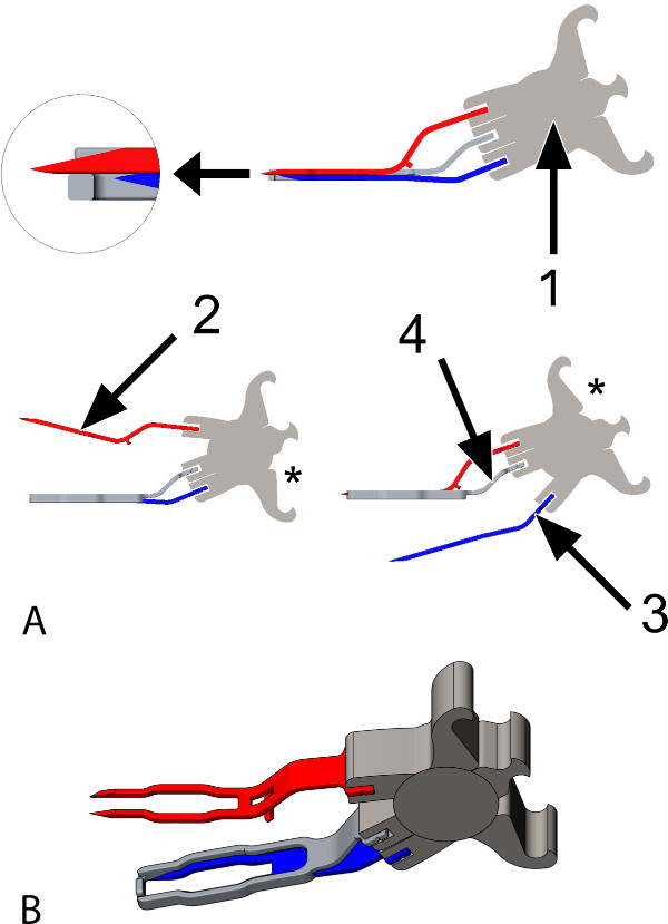
Figure 1: The Trinity Clip. (A) Animated images of the coronary anastomotic connector, a side view. The connector is constructed of titanium and is suitable for target coronary arteries with an inner diameter (ID) between 1.4 and 1.6 mm. The connector consists of: 1: A spring, which enables the 2 forks to open and close, individually one by one (lower left and right panel), by placing an applicator into 1 of the shafts of the spring (see asterisks, applicator not shown). Additionally, it provides active compression of the 2 forks. 2 and 3: Two forks with each 2 sharp pins, attached to the spring (1); the upper fork (2, red) will be inserted into the graft, the lower fork (3, blue) will be inserted into the coronary artery. 4: An extravascular band (2 times the thickness of the pins; illustrated transparently in the upper panel), adjacent to the forks over their full length, hereby obtaining extra lateral compression. It is attached to the spring, in between the anchor-points of the forks. While opening the lower fork (3, blue; lower right), the upper fork (2, red) maintains compression (of the graft) onto the band (4). The magnified subsection (top left) demonstrates the position of the tip of the longer upper fork (2, red) in an indentation at the front of the extravascular band (4). (B) Animated image of the connector, a diagonal top view. The upper fork is opened (applicator not shown).
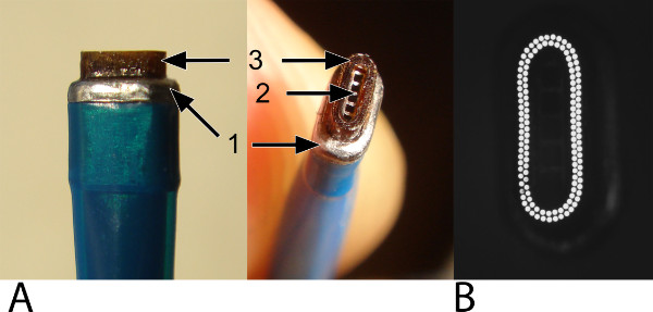
Figure 2: The oval laser catheter. The oval laser catheter is used for the laser-punched arteriotomy into the graft and the coronary artery. Please note that the laser catheter does not weld or seal the anastomosis. (A) The outer band (1; widest part) facilitates positioning and stabilization into the anastomotic connector and provides safety (i.e., it prevents the laser catheter of slipping through the connector and damaging the inferior wall of the coronary artery). The vacuum channel (2) is located centrally and is surrounded by laser fibers (3). (B) A top view at the tip of the laser catheter. A row of 2 laser fibers is visualized.
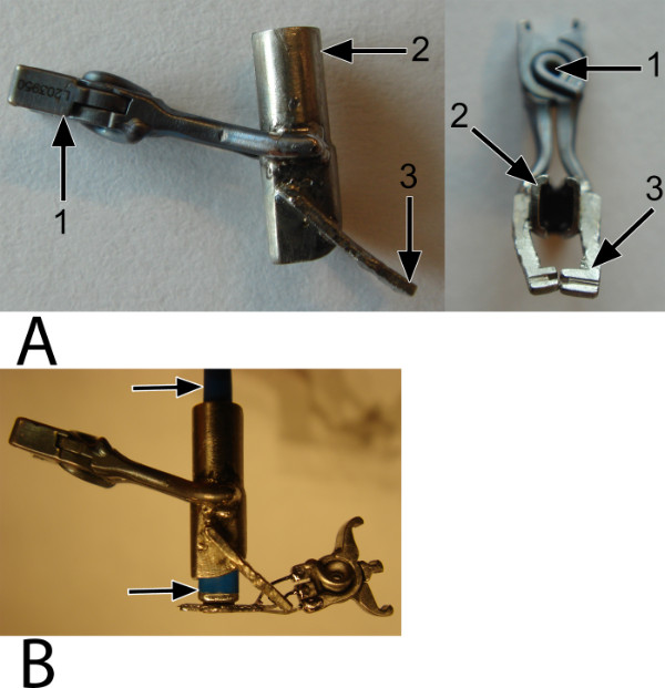
Figure 3: The fixation clip. An external, temporary fixation clip is used to fixate and stabilize the laser catheter into the mounted anastomotic connector, ensuring proper perpendicular positioning of the catheter during the anastomosis construction. (A) A side view (left) and an inferior view (right). The spring (1) provides force onto both the shell (2), which holds the catheter, and the bars (3), which catch the connector. (B) The arrows point at the catheter, which is perpendicularly fixated by the fixation clip and forms a stabilized complex with the connector and the graft (not shown).
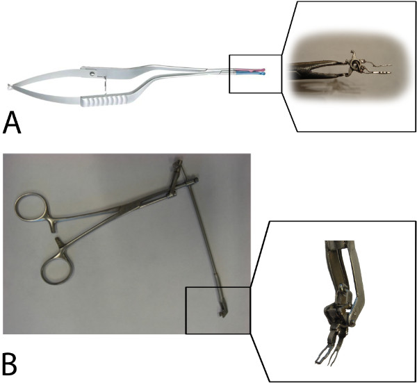
Figure 4: The applicators. (A) A standard Aneurysm clip applier controls the upper fork via the lower application shaft of the spring (see the subsection) and, in addition, the fixation clip. (B) A prototype VasCo applicator controls the lower fork via the upper application shaft of the spring (see the subsection).
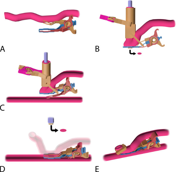
Figure 5: The coronary anastomosis procedure with the Trinity Clip System. (A) Mounting of the coronary anastomotic connector: an applier (not shown) is used to insert the upper fork of the connector into the lumen of the perfused graft, directed distally. Note: by releasing the applicator, the connector closes and actively compresses the graft between the 2 forks and the extravascular band. (B) The mounted and laser-punched graft. The laser catheter is introduced intravascularly, through the distal free end of the graft, into the connector, and is perpendicularly fixated by the external fixation clip. The graft is laser-punched. The arrow points at the laser-punched fragment of the graft (i.e., “flap”). (C) Nonocclusive connection of the graft to the coronary: an applier (not shown) is used to insert the lower fork. The fork punctures the coronary wall and is fully inserted into the lumen of the perfused coronary, directed distally. During the insertion, the upper fork maintains compression of the graft onto the extravascular band, ensuring proper fixation of the graft during this maneuver, while the fixation clip ensures proper perpendicular positioning of the laser catheter. (D) Laser-punched arteriotomy of the coronary artery: the connector is closed and compresses both vessel walls (i.e., graft and coronary artery) between the 2 intraluminal forks and the extravascular band. The coronary wall is laser-punched by the fixated catheter, perpendicularly positioned onto the coronary artery wall. Subsequently, the fixation clip is removed and the catheter retracted, including the retrieved flap (see arrow). (E) Final anastomosis. A ligating hemoclip is placed at the distal end of the graft. Note: The complete connector stays in situ and is not removed after anastomosis construction.
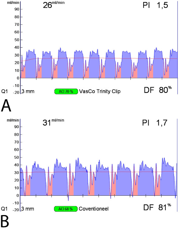
Figure 6: Intraoperative transit time flow measurements of the Trinity Clip facilitated left internal thoracic artery (LITA)-to-left anterior descending artery (LAD) anastomosis and a conventional hand-sutured LITA-to-LAD anastomosis. Both the facilitated (A) and the hand-sutured (B) LITA-to-LAD bypass show a normal appealing flow curve, a PI below 5, and a predominant diastolic graft filling (diastolic filling [DF] 80%) with minimal systolic peaks, suggestive for a patent coronary graft.
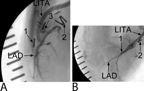
Figure 7: Five-week coronary angiogram of the Trinity Clip facilitated left internal thoracic artery (LITA)-to-left anterior descending artery (LAD) anastomosis (an example of the preclinical study). (A) A lateral-side view. Ligating hemoclips are placed at the distal end of the LITA (1) and proximal native LAD (2). The connector (3) can be only seen at the side view. Note, coverage of the forks and extravascular band of the connector by non-radiopaque matter is seen. The distal end of the LITA is not filled with contrast, suggesting remodeling by streamlining neointima. (B) A top view.
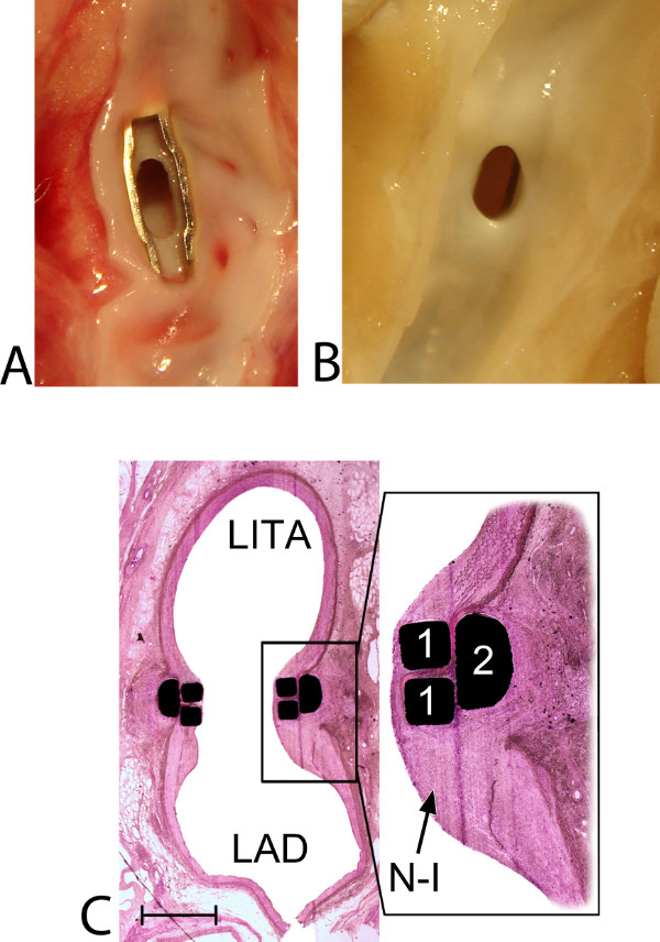
Figure 8: Healing and remodeling of the Trinity Clip facilitated left internal thoracic artery (LITA)-to-left anterior descending artery (LAD) anastomosis: macroscopic and histological view. (A) Macroscopic view from inside the LAD at 5 hr follow-up. A patent anastomosis without any intraluminal thrombus formation is demonstrated. The lower fork of the connector is positioned intraluminally, without capturing or damaging the lateral or inferior coronary wall. A small and sharp laser-cut edge (0.1 mm), of both the LITA and the LAD, is visible in between the forks, and both vessel walls are positioned exactly on top of each other, without overlapping adventitial tissue. (B) Macroscopic view from inside the LAD at 5-week follow-up (an example of the preclinical study). A patent anastomosis is demonstrated and the intraluminal forks and the laser edge are completely covered by a tissue layer, without narrowing the anastomotic orifice. (C) Histologic transversal section, mid-anastomosis, at 5-week follow-up (12.5X magnified; an example of the preclinical study). Streamlining coverage of the (initially intraluminally exposed) forks (1) of the connector by neo-intima (N-I) is visible. The magnified subsection (40X magnification) demonstrates the retracted and remodeled laser edge. Between the forks and the extravascular band, compression of the arterial wall is seen without adverse remodeling (e.g., erosion, luxation, or pseudoaneurysm formation). Moreover, the inferior wall is unaffected, without any intimal hyperplasia reactions (which could be suggestive for [laser-] damage), and no excessive inflammatory cell reactions are found (which could potentially be triggered by the foreign body implant). The distal end of the LITA, the ‘cul de sac’, is filled with organized thrombus, covered by neointimal tissue, streamlining the anastomosis (not shown). Finally, the spring of the connector is fully integrated, extravascularly, between the LITA and LAD, without erosion effects or damage to the adjacent arterial walls (not shown). Note: interruption of the inferior coronary wall is caused by longitudinally opening of the coronary artery before inspection. A scale bar (1 mm) is provided in the left lower corner.
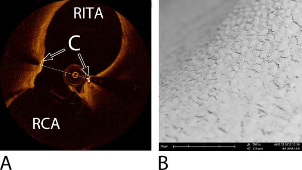
Figure 9: Examples of an intracoronary Optical Coherence Tomography (OCT) image of a right internal thoracic artery (RITA)-to-right coronary artery (RCA) anastomosis and a Scanning Electron Microscope (SEM) image of a left internal thoracic artery (LITA)-to-left anterior descending artery (LAD) anastomosis. Both were constructed with a predecessor ELANA coronary connector6,7. (A) An OCT image at 6-month follow-up, transverse section, mid-anastomosis7. Note: the OCT wire is visible in the lumen. The transversal line represents the minimal anastomotic width (= 2.2 mm). C = connector; RITA = right internal thoracic artery; RCA = right coronary artery. (B) A detailed SEM image at the level of the fork of the connector demonstrating complete coverage with endothelium (2,080X magnification), at 6-month follow-up6,7.
Discussion
This paper describes a novel coronary anastomotic connector, the Trinity Clip, and how to evaluate such a new device in a porcine off-pump bypass model. Different techniques are proposed to assess the quality of an anastomosis, facilitated by the new connector or conventionally constructed: intraoperative, postoperative, and post-mortem techniques. Assessment of the quality and safety of the facilitated anastomosis — as well as the healing and remodeling process — at the short- and long-term is of utmost importance prior to future clinical application of the coronary anastomotic connector.
Currently, only 1 coronary anastomotic connector is being used clinically17,18, multiple other devices demonstrated unfavorable experimental or clinical results, or developers failed to market the product19-21. Compared to other methods to facilitate the coronary anastomosis, the Trinity Clip includes several interesting features. First, owing to the nonocclusive connection of the vessel walls, coronary conditioning (i.e., snaring or shunting) is redundant, enabling anastomotic construction in a bloodless field without a time constraint, and hence, reducing manipulation of the coronary artery. Second, the construction is relatively simple and straightforward, neither a separate incision into the coronary artery nor placing additional stitches to obtain hemostasis are necessary. Third, the connector is a low-profile device, without a bulky device-deployment system; thus, it will not hamper the bypass construction on difficult to reach or remote areas of the heart, and, so, it will potentially extend the possibilities for revascularization via minimally invasive approaches.
Important questions regarding the biological behavior of the facilitated anastomosis are yet unanswered. What are the effects of laser-punching the arteriotomy into both the ITA and the LAD? Could the blood-exposed non-intimal surface (i.e., the material of the forks and the medial and adventitial laser rim), in relation to the small dimension target coronary, be a potential limitation by excessive intimal hyperplasia formation on the long-term? To answer these questions, a preclinical study, using the porcine model as described in this paper, will assess the long-term patency and, additionally, the healing and remodeling effects regarding intimal hyperplasia formation with subsequent potential narrowing of the anastomosis. Moreover, in this preclinical study, the patency, healing, and remodeling of the facilitated anastomosis will be compared to the control, conventionally hand-sutured, anastomosis. The porcine model is suitable for these research questions because of its to human resembling physiology and anatomy of the heart and coronary arteries, and its expedite healing response (e.g., intimal hyperplasia formation), in which a 6 months follow-up duration in the porcine model is comparable to 1.5-3 years of follow-up of the stented human coronary artery22. However, the arteries of the young and healthy pig are not diseased and compliant, and thus different to the human diseased vessels encountered in cardio-thoracic surgical practice. Therefore, prior to clinical introduction, the feasibility and safety of the connector will be also evaluated in a human atherosclerotic cadaveric model. Furthermore, a tendency to hypercoagulability is found in pigs23. Therefore, to assess facilitated anastomoses on small caliber coronaries, the porcine model is quite challenging. To this point, the in this protocol described antiplatelet therapy (75 mg clopidogrel and 320 mg acetylsalicylic acid) is justified. In addition, the antiplatelet regimen is in anticipation of the blood-exposed nonintimal surface of the anastomosis (BENIS). In our previous study, we showed that the anastomotic nonintimal surface of a predecessor coronary connector completely endothelialized after 10 days6,7. The role for antiplatelet therapy in clinics, using this connector, should be based on the rate of endothelialization. Once the nonintimal surface is endothelialized, the antiplatelet regimen might be lowered.
The excimer laser is a contact laser and will only successfully laser-punch the vessel wall in the case there is full direct circumferential laser-tissue contact. The most critical step in the anastomosis construction, therefore, is the correct position of the laser catheter onto the vessel wall of the graft and the coronary artery. This step has to be trained on ex vivo cadaver models (e.g., pig heart) to minimize the learning curve. Possible scenarios that will result in a flap retrieval failure of the laser, and which should be taken into mind, are described here: 1) The coronary anastomotic connector is designed to connect the graft to the coronary artery, and secondly, to serve as a laser platform. The connector presents the vessel walls (i.e., a straight tissue surface, without bumps) and allows a perpendicular position of the catheter onto the vessel wall. If the connector is mal-positioned (e.g., incomplete insertion, back- or sidewall capture, intramural or –adventitial positioning), the vessel wall presentation is suboptimal (i.e., no straight surface). Hence, in the case of a mal-position, one should always reposition the connector before to the point of no return (i.e., the arteriotomy). 2) The fixation clip is designed to keep the laser catheter perpendicular into the connector during the construction. However, the fixation clip is not designed to resist lots of contra-force, so the surgeon has to support the laser catheter during the construction. If not sufficiently supported, the catheter can dislocate. 3) To ensure optimal laser-tissue contact, the coronary wall has to be dissected free of loose peri-adventitial tissue, towards the lateral wall. Be sure that the laser surface only consists of the coronary wall, from its intima up to its adventitia, and no peri-adventitial tissue is captured into the connector.
If unfortunately the anastomotic construction fails, one should retract the clip (by opening of the lower fork only) and then close the coronary lesion (±2 mm length) with repair sutures (8-0 prolene). Pigs are usually quite sensitive to ischemic stress. Therefore, ischemic preconditioning is recommended before occluding the coronary for repairing the defect. Subsequently, a new anastomosis can be constructed distal to the first target. The graft is still mounted by the upper fork of the connector. So after catheter re-positioning and fixation, the connector can be directly inserted into the coronary artery.
The most important anastomosis evaluation techniques are the coronary angiogram (clinical gold standard) and histology (experimental gold standard, combined with the coronary angiogram). However, intraoperative quality assessment of the anastomosis by transit time flow measurements (TTFM) is extremely informative. TTFM is fast, non-invasive, real-time, and easy, and moreover, correct interpretation can reduce the number of technical, not visible, errors11,12,24-26. The modern TTFM consoles automatically calculate and demonstrate real-time the mean flow, the flow curve, and the pulsatility index (PI), and lots of other parameters. The PI is calculated by (max flow-min flow) / mean flow and is an indicator of the quality of the anastomosis, whereas the mean flow on its own is not a reliable indicator. A low mean flow (<15 ml/min) with a good PI (<5) and a good diastolic flow curve can be found by a perfect anastomosis at a small target coronary with a moderate run-off, whereas a good mean flow (>15 ml/min) with an abnormal diastolic filling pattern and a high PI (>5) is suggestive of an anastomotic imperfection or a graft failure (i.e., torsion, compression, or kinking of the graft). In this case, one should consider revising the anastomosis. Thus, a good assessment of the quality of the anastomosis should include the interpretation of the flow curve, the pulsatility index, and the mean flow, combined with the clinical status. However, the reported specificity and sensitivity of TTFM are not uniform, and, therefore, the diagnostic accuracy is under debate. In addition, the cut-off value of the PI is empirically determined on the basis of clinical experience rather than clinical studies. The TTFM console we currently use in the preclinical animal study disposes of epicardial ultrasound imaging. If there is still uncertainty regarding the quality of the anastomosis after the flow measurements, a real-time epicardial ultrasound image can be of great help in further evaluation of the anastomosis, hereby increasing the diagnostic accuracy27-31.
An experimental alternative to the TTF measurements is the peak hyperemic flow response32, i.e., coronary flow reserve, which is the ratio of the peak hyperemic flow, following 30-second graft occlusion, and the base flow. The peak hyperemic flow response should be >4 for a distal anastomosis. If the anastomosis is targeted proximal on the coronary artery, the peak hyperemic flow response can be slightly lower and should be >36. An absent hyperemic flow response is suggestive for a technical anastomotic error or a graft failure. In that case, consult the TTF measurements and clinical status, and consider revising the anastomosis. Please note that the absolute flow reserve varies with the arterial pressure (thus, always measure at the same mean arterial pressure, in duplicate) and that ischemic preconditioning can negatively influence the peak hyperemic flow response. Furthermore, the peak hyperemic flow response is not a validated method and an absolute cut-off value has not been defined. We have empirically selected the cut-off on the basis of our experimental experience.
Finally, the anastomosis technique described in this protocol is an experimental anastomotic technique with the aim and potential to be applied in the clinical minimally invasive setting. Currently, the materials for the application of the technique shown in this paper are not finalized or market-ready products, but rather prototype instruments. There is still a window of amelioration (e.g., versatile applier and flexible laser catheter), which will be filled in soon. This new technology has interesting potential, and will be evaluated thoroughly in a preclinical study by using this protocol.
Açıklamalar
The authors have nothing to disclose.
Acknowledgements
This study was supported by the University Medical Center Utrecht, Vascular Connect b.v., and EuroTransBio, project ELANA Keyhole (ETB110014). Medistim provided the VeriQ C console, and reduced prices for the ultrasound and flow probes were billed. We acknowledge the constructive contributions of Evelyn Velema, Marlijn Jansen, Joyce Visser, Grace Croft, Martijn van Nieuwburg, Cees Verlaan, Rik Mansvelt Beck, Sander van Thoor, André van Dieren, and colleagues from the Utrecht University Central Animal Facilities.
Materials
| Name of Material/ Equipment | Company | Catalog Number | Comments/Description |
| Trinity Clip | Vascular Connect b.v., Utrecht, The Netherlands | Initial Prototype and Proprietary Design | |
| Excimer Laser System CVX-300 | Spectranetics Corp., Colorado Springs, CO | ||
| Oval laser catheter | Vascular Connect b.v., Utrecht, The Netherlands | Initial Prototype and Proprietary Design | |
| Silicon Extension Tube (vacuum tube) | Medela, Baar, Switzerland | ||
| Medela Dominant 50 Pump (vacuum pump) | Medela, Baar, Switzerland | ||
| Fixation clip | Vascular Connect b.v., Utrecht, The Netherlands | Initial Prototype and Proprietary Design | |
| Standard Aneurysm clip applier | Peter Lazic, GmbH, Tuttlingen, Germany | ||
| VasCo applicator | Vascular Connect b.v., Utrecht, The Netherlands | Initial Prototype and Proprietary Design | |
| Microvascular Acland clamp B-3V | S&T Marketing Ltd, Neuhausen,Switzerland | ||
| Aneurysm clip Yasargil-type, curved, 9 mm | Scanlan International, Inc, Saint Paul, Minn | ||
| Weck Hemoclip | Teleflex Medical, Research Triangle Park, NC | ||
| Hemochron Signature Elite | International Technidyne Corporation (ITC), Edison, NJ, USA | ||
| Hemochron Jr. Activated Clotting Time Plus (ACT+) (cartridge) | International Technidyne Corporation (ITC), Edison, NJ, USA | ||
| Arteriotomy shunt | Medtronic, Inc, Minneapolis, Minn | ||
| Octopus Evolution AS (cardiac tissue stabilizer) | Medtronic, Inc, Minneapolis, Minn | ||
| VeriQ C (TTFM and epicardial ultrasound) | Medi-Stim ASA, Oslo, Norway | ||
| Allura Xper FD20 | Philips, Eindhoven, the Netherlands | ||
| Combowire | Volcano Corporation, San Diego, CA, USA | ||
| ComboMap system | Volcano Corporation, San Diego, CA, USA | ||
| C7 Dragonfly (frequency domain optical coherence tomography (OCT) system) | LightLab Imaging, Inc., Westford, MA | ||
| AnalySiS (software package) | Soft-Imaging Software GmbH, Münster, Germany | ||
| Philips XL30LAB (scanning electron microscope) | FEI Europe, Eindhoven, The Netherlands |
Referanslar
- Halkos, M. E., Puskas, J. D. Off-pump coronary surgery: where do we stand in 2010. Curr Opin Cardiol. 25, 583-588 (2010).
- Lapierre, H., Chan, V., Sohmer, B., Mesana, T. G., Ruel, M. Minimally invasive coronary artery bypass grafting via a small thoracotomy versus off-pump: a case-matched study. Eur J Cardiothorac Surg. 40, 804-810 (2011).
- Tulleken, C. A. F., et al. Blood vessel connectors and methods for blood vessel connection. US patent. , (2013).
- Van Thoor, A. C. E., Stecher, D., Keizer, D. M. Catheter apparatus and method. US patent. , (1995).
- Stecher, D., et al. A new nonocclusive laser-assisted coronary anastomotic connector in a rabbit model. J Thorac Cardiovasc Surg. 145, 1124-1129 (2013).
- Stecher, D., et al. The nonocclusive laser-assisted coronary anastomotic connector in an off-pump porcine bypass model. J Thorac Cardiovasc Surg. 147, 1390-1397 (2014).
- Stecher, D., et al. Six-Month Healing of the Nonocclusive Coronary Anastomotic Connector in an Off-Pump Porcine Bypass Model. Innovations (Phila). 9, 130-136 (2014).
- Tulleken, C. A., Verdaasdonk, R. M., Berendsen, W., Mali, W. P. Use of the excimer laser in high-flow bypass surgery of the brain). J Neurosurg. 78, 477-480 (1993).
- Doormaal, T. P., et al. Patency, flow, endothelialization of the sutureless Excimer Laser Assisted Non-occlusive Anastomosis (ELANA) technique in a pig model. J Neurosurg. 115, 1221-1230 (2011).
- Buijsrogge, M. P., Grundeman, P. F., Verlaan, C. W., Borst, C. Unconventional vessel wall apposition in off-pump porcine coronary artery bypass grafting: low versus high graft flow. J Thorac Cardiovasc Surg. 123, 341-347 (2002).
- Walpoth, B. H., et al. Transit-time flow measurement for detection of early graft failure during myocardial revascularization. Ann Thrac Surg. 66, 1097-1100 (1998).
- Ancona, G., Karamanoukian, H. L., Salerno, T. A., Schmid, S., Bergsland, J. Flow measurement in coronary surgery. Heart Surg Forum. 2, 121-124 (1999).
- Lovstakken, L., et al. Blood flow imaging: a new two-dimensional ultrasound modality for enhanced intraoperative visualization of blood flow patterns in coronary anastomoses. J Am Soc Echocardiogr. 21, 969-975 (2008).
- Koudstaal, S., et al. Assessment of coronary microvascular resistance in the chronic infarcted pig heart. J Cell Mol Med. 17, 1128-1135 (2013).
- Agostoni, P., Stella, P. R. Optical coherence tomography: new (near-infrared) light on stent implantation. Heart. 95, 1895-1896 (2009).
- Scheltes, J. S., van Andel, C. J., Pistecky, P. V., Borst, C. Coronary anastomotic devices: blood-exposed non-intimal surface and coronary wall stress. J Thorac Cardiovasc Surg. 126, 191-199 (2003).
- Balkhy, H. H., Wann, L. S., Arnsdorf, S. Early patency evaluation of new distal anastomotic device in internal mammary artery grafts using computed tomography angiography. Innovations. 5, 109-113 (2010).
- Matschke, K. E., et al. The Cardica C-Port System: clinical and angiographic evaluation of a new device for automated, compliant distal anastomoses in coronary artery bypass grafting surgery–a multicenter prospective clinical trial. J Thorac Cardiovasc Surg. 130, 1645-1652 (2005).
- Suyker, W. J., et al. Stapled coronary anastomosis with minimal intraluminal artifact: The S2 Anastomotic System in the off-pump porcine model. J Thorac Cardiovasc Surg. 127, 498-503 (2004).
- Carrel, T., et al. Clinical and angiographic results after mechanical connection for distal anastomosis in coronary surgery. J Thorac Cardiovasc Surg. 127, 1632-1640 (2004).
- Filsoufi, F., et al. Automated distal coronary bypass with a novel magnetic coupler (MVP system). J Thorac Cardiovasc Surg. 127, 185-192 (2004).
- Fischell, T. A., Virmani, R. Intracoronary brachytherapy in the porcine model: a different animal. Circulation. 104, 2388-2390 (2001).
- Kostering, H., Mast, W. P., Kaethner, T., Nebendahl, K., Holtz, W. H. Blood coagulation studies in domestic pigs (Hanover breed) and minipigs (Goettingen breed). Lab Anim. 17, 346-349 (1983).
- Ancona, G., et al. Graft revision after transit time flow measurement in off-pump coronary artery bypass grafting. Eur J Cardiothorac Surg. 17, 287-293 (2000).
- Di Giammarco, G., et al. Predictive value of intraoperative transit-time flow measurement for short-term graft patency in coronary surgery. J Thorac Cardiovasc Surg. 132, 468-474 (2006).
- Kieser, T. M., Rose, S., Kowalewski, R., Belenkie, I. Transit-time flow predicts outcomes in coronary artery bypass graft patients: a series of 1000 consecutive arterial grafts. Eur J Cardiothorac Surg. 38, 155-162 (2010).
- Haaverstad, R., et al. Intraoperative color Doppler ultrasound assessment of LIMA-to-LAD anastomoses in off-pump coronary artery bypass grafting. Ann Thorac Surg. 74, 1390-1394 (2002).
- Klein, P., Meijer, R., Eikelaar, J. H., Grundeman, P. F., Borst, C. Epicardial ultrasound in off-pump coronary artery bypass grafting: potential aid in intraoperative coronary diagnostics. Ann Thorac Surg. 73, 809-812 (2002).
- Dessing, T. C., et al. Geometry assessment of coronary artery anastomoses with construction errors by epicardial ultrasound. Eur J Cardiothorac Surg. 26, 257-261 (2004).
- Budde, R. P., Meijer, R., Dessing, T. C., Borst, C., Grundeman, P. F. Detection of construction errors in ex vivo coronary artery anastomoses by 13-MHz epicardial ultrasonography. J Thorac Cardiovasc Surg. 129, 1078-1083 (2005).
- Di Giammarco, G., et al. Intraoperative graft verification in coronary surgery: increased diagnostic accuracy adding high-resolution epicardial ultrasonography to transit-time flow measurement. Eur J Cardiothorac Surg. , (2013).
- Pijls, N. H. J., et al. Coronaire fysiologie en myocardischemie. Cardiologie. 2, 169-170 (2008).

