Generating a Blood-Brain Barrier Chip Using iPSC-derived Precursor Cells
Abstract
Source: Jagadeesan, S., et al., Generation of a Human iPSC-Based Blood-Brain Barrier Chip. J. Vis. Exp. (2020).
This video showcases creating a blood-brain barrier chip using iPSC-derived precursor cells. It involves seeding neural progenitor cells and brain microvascular endothelial cells in separate channels with a porous membrane. By flowing differentiation media, the endothelial cells form tight junctions resembling blood vessels, and the neural cells mature into various brain cell types, establishing a functional blood-brain barrier on the chip.
Protocol
1. Generation of iPSC-derived neural progenitor cells (iNPCs)
- Produce EZ-spheres from iPSC colonies as described below and as previously published.
- Culture iPSC colonies to confluency on basement membrane matrix-coated 6 well plates (0.5 mg/plate) in mTESR1 or other commercial media (see Table of Materials).
- Remove iPSC medium and replace with 2 mL of EZ-sphere medium [ESM; DMEM:F12 7:3 supplemented with 100 ng/mL basic fibroblast growth factor (bFGF), 100 ng/mL epidermal growth factor, 5 µg/mL heparin, and 2% B27 supplement].
- Scrape the bottom of each confluent well with the back of a sterile 1000 µL pipette tip or cell scraper.
- Collect all cells and place them in an ultra-low attachment T25 flask to allow the spontaneous formation of free-floating spheres. Incubate overnight at 37 °C.
- Feed the spheres every 2–3 days when the medium turns yellow by replacing half of the medium with fresh ESM. This allows for spheres to remain in conditioned medium, which is highly important for their growth and maintenance.
- Lean the flask on a tube rack and allow the spheres to settle by gravity for 1–2 min down to the corner of the flask.
- Once settled, aspirate half of the supernatant with a 5 mL or 10 mL serological pipette and replace it with fresh, pre-warmed ESM.
- Passage EZ-spheres weekly by chopping spheres to 200 μm diameters as previously described. EZ-spheres can be maintained for up to 25 passages and are ideal when used between passages 8–25.
- Prepare single-cell suspension of iNPCs:
- To induce neural differentiation, dissociate the EZ-sphere into single cells.
- Collect spheres 3–4 days post-chopping from a T75 flask and transfer them into a 15 mL conical, then let it stand for 2 min or until all spheres are settled at the bottom.
- Slowly remove ESM with a 5 mL pipette without disrupting the settled spheres. Add 1 mL of dissociation solution (see Table of Materials) and incubate for 10 min at 37 °C.
- Swirl the dissociation solution and spheres after 5 min of incubation to ensure that any settled spheres are treated.
- Slowly remove the dissociation solution. Add 1 mL of neural differentiation medium [NDM; DMEM: F12 with 2% B27 minus vitamin A, 1% N2 supplement, and human brain-derived neurotrophic factor (hBDNF, 20 ng/mL)].
- Triturate the spheres into single cells by pipetting using a 1 mL pipette followed by a 200 µL pipette, until all spheres have dissociated. Avoid bubble formation during the trituration procedure.
- Count dissociated cells using a hemocytometer and dilute cells to a final density of 1 x 10⁶ cells/mL. It is possible to change the density depending on the application.
NOTE: Higher densities (up to 6 x 10⁶ cells/mL) are recommended for short-term cultures of up to 3 days, and lower densities are recommended for long-term applications of up to 3 weeks.
NOTE: Cells are now ready to seed into the top channel of the chip to form the "brain side".
2. Differentiation of iPSCs into iBMECs
- Passage iPSCs from a single confluent well of a 6-well plate at a 1:6 ratio into a 6-well basement membrane matrix-coated plate. Let cells adhere for 24 h. Change the iPSC medium daily.
- Count cells daily using a hemocytometer.
- When cells reach a density of 1.5–3.0 x 10⁵ cells/well, replace iPSC medium with 3 mL of unconditioned medium without bFGF [DMEM:F12 1:1, with 10% knockout serum replacement (KOSR), 1% non-essential amino acids (NEAA), 0.5% glutamine supplement (Table of Materials), and 100 µM β-mercaptoethanol]. Replace medium daily for 6 days.
- At day 6, replace medium with endothelial cell (EC) medium [human endothelial serum free medium (hESFM) supplemented with 1% platelet-poor plasma-derived bovine serum, 20 ng/mL bFGF, and 10 µM all-trans retinoic acid (RA)]. Leave medium for 2 days.
- Remove EC medium and add 1 mL of dissociation solution per well. Incubate at 37 °C for 35 min.
NOTE: While this is considered a long incubation time in the dissociation solution used here, iBMECs can endure this treatment with cell viability higher than 90%. - Detach the cells from the well by gently pipetting the cell suspension and collecting all cells into a 15 mL conical tube.
NOTE: Avoid harsh pipetting. If cells do not detach easily, incubate for an additional 5 min. - Add 1 volume of EC medium to the 15 mL conical to inactivate Accutase, centrifuge at 200 x g for 5 min, remove the medium, and replace it with 1 mL of EC medium (without bFGF and RA).
- Count cells using a hemocytometer and adjust cell density to 14–20 x 106 cells/mL.
NOTE: Cells are now ready to be seeded into the bottom channel of the chip to form the "blood side".
3. Microfabrication of the organ chip
- Use an organ chip for the BBB chip model and its production as done previously. The tall channel organ chip (see Table of Materials) is fabricated from a highly flexible polydimethylsiloxane (PDMS) elastomer that contains two superimposed and parallel micro-scale channels separated by a flexible porous membrane. The top and bottom microchannel sizes are 1 mm x 1 mm and 1.0 mm x 0.2 mm, respectively. The two channels are separated by a 50 μm thick PDMS-made flexible porous membrane, containing 7 μm diameter pores with 40 μm spacing. The surface area of the porous membrane that separates the channels is 0.171 cm2.
4. Chip preparation
- Organ chips are supplied prepackaged within the chip carrier, eliminating the need to disturb or distort the chip alignment during handling. In addition, the chip carrier connects securely to a portable module ("Pod") that acts as the interface between the culture module and the chip.
- Spray the packaging of the chips with 70% ethanol and bring them into the biosafety cabinet (BSC).
- Open the packaging and lay out the organ chip in a sterile Petri dish. Handle the chip carrier only by the sides to avoid direct contact with the chip.
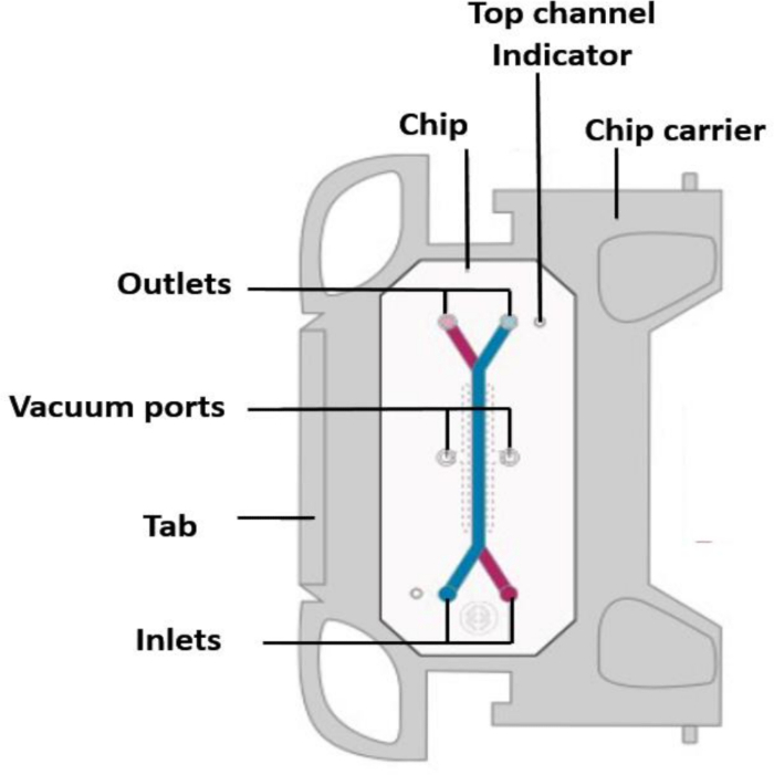
- Ensure that the tab of the carrier is facing to the right (Figure 1), and when using multiple chips, align them all in the same orientation.
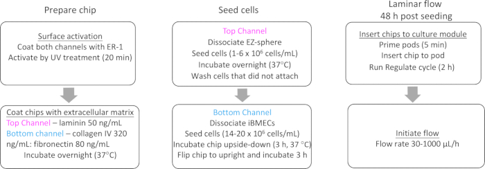
- Label each chip on the carrier tab (complete chip preparation and workflow are shown in Figure 2).
5. Surface activation and ECM coating
- Preparation of surface activation solution
- Emulate reagent 1 (ER-1), provided in a vial containing 5 mg, is light-sensitive. Prepare fresh ER-1 solution immediately before use. ER-1 integrity is crucial in the successful preparation of the chips.
- Turn off the light in the BSC when handling ER-1.
NOTE: ER-1 is an eye irritant and must be handled in the BSC with proper gloves and eye protection. - Allow the ER-1 and ER-2 reagents to equilibrate to room temperature (RT) before use.
- Protect the solution from light by wrapping an empty sterile 15 mL conical tube with foil.
- In the BSC, briefly tap the ER-1 vial to settle the powder at the bottom.
- Add 1 mL of ER-2 buffer to the vial, and immediately transfer its content to the bottom of the 15 mL wrapped conical tube. Do not pipette to mix. The color of the solution transferred to the conical tube will be red.
- Repeat step 5.1.6 3x. On the last round, cap the ER-1 vial and invert to collect any remaining powder from the lid, then transfer the solution to the conical tube; this will bring the total volume to 4 mL of ER-1 solution.
- Add 6 mL of ER-2 solution to the 4 mL of ER-1 solution in the 15 mL conical tube to a final concentration of 0.5 mg/mL. ER-1 should be fully dissolved within the ER-2 solution.
- Surface activation
- Utilizing a P200 pipette and a sterile 200 μL filtered pipette tip, take up 200 μL of ER-1 mixture.
- Place the pipette in the bottom inlet and push 20 μL of ER-1 mixture through the bottom channel until the mixture starts to flow out of the bottom channel outlet.
- Add approximately 50 μL of ER-1 mixture and place it in the top channel inlet. Push the mixture through the top channel until it starts to flow out of the top channel outlet.
- Remove all excess ER-1 mixture from the surface of the chip by gentle aspiration. Make certain the ER-1 mixture is only removed from the chip surface and not from the channels.
- Verify that the channels are free of air bubbles before ultraviolet (UV) activation. If air bubbles are detected, remove bubbles by washing the channel with ER-1 mixture.
- Place the open dish containing the chips into the UV light box (provided by Emulate Inc.).
- Set the switch at the back of the UV light box to the "Consistent" setting. Turn on the power and initiate UV activation. Leave the chips under UV light for 20 min.
NOTE: Avoid exposure of personnel to UV light. - Remove the ER-1 mixture from both channels.
- Wash each channel with 200 μL of ER-2 solution.
- Remove ER-2 from both channels.
- Wash each channel with 200 μL of sterile cold Dulbecco's phosphate-buffered saline (DPBS).
- Leave cold DPBS inside the channels until proceeding to the next step.
- Extracellular matrix (ECM) preparation and coating
- Prepare the ECM solution by combining the individual ECM components with cold DPBS, water, or other solvent to the final working concentrations. The ECM solution should be prepared fresh each time it is used.
- Coat both top and bottom channels of the chip with ECM, with composition as determined by the cell type to be seeded. ECM mixture must be maintained on ice until use.
- Use laminin (50 µg/mL) to coat the "brain side", and collagen IV and fibronectin mixed at a 4:1 ratio (320:80 µg/mL) to coat the "blood side" as described in section 5.6.
- Preparation of ECM aliquots
- Dilute 1 mg/mL laminin in cold DPBS to a final concentration of 50 µg/mL. Aliquot and store at -20 °C until use.
- Dissolve collagen IV in 0.1% acetic acid to a concentration of 1 mg/mL. Incubate the solution at 2–8 °C overnight or at RT for 1-3 h or until fully dissolved.
- Prepare a 1 mL mixture of collagen IV:fibronectin (320 µL of collagen IV, 80 µL of fibronectin, 600 µL of sterile double-distilled H2O). The mixture can be stored at -20 °C.
- Coating the chips with ECM
- Fully aspirate the cold DPBS from both channels. Set a P200 pipette to take up 100 μL of collagen IV:fibronectin solution.
- Introduce the solution through the bottom channel inlet until a small droplet forms on the outlet. Leave a small droplet on the inlet after removing the pipette tip.
- Introduce the laminin solution through the top channel inlet until a small droplet forms on the outlet. Leave a small droplet on the inlet after removing the pipette tip.
- Look closely at the channels to ensure that no bubbles are present. If bubbles are present, wash the channel with the appropriate ECM solution until all bubbles are removed.
- Repeat steps 5.5.1–5.5.4 for each chip.
- Add 1.5 mL of DPBS to the cap of a 15 mL conical tube. Place the DPBS cap in the 150 mm culture dish with the chips to provide extra humidity and seal the dish with parafilm. For best results, incubate the chips at 4 °C overnight.
NOTE: If desired, cells can be seeded the same day as chip activation and ECM coating, though overnight incubation is preferred. Chips can be ready for seeding 4 h after adding the ECM and incubating chips at 37 °C.
6. Seeding the "brain side" channel and differentiating EZ spheres into mixed neural cultures
- Bring the dish containing the prepared chips to the BSC. Gently wash both channels with 200 µL of NDM.
- Avoiding contact with the ports, carefully aspirate excess media droplets from the surface of the chip. Gently agitate cell suspension before seeding each chip to ensure a homogeneous cell suspension
- Seeding the iNPCs into the top channel to generate the "brain side"
- Seed the cells (1 x 10⁶ cells/mL) into the top channel of the chip. Add a P200 tip containing 30–100 μL of cell suspension to the top channel inlet and gently release the tip from the pipette. Take an empty P200 pipette, depress the plunger, insert it into the top channel outlet, and carefully pull the single-cell suspension through the chip.
- Cover the dish and transfer to the microscope to check the seeding density and homogenous distribution of cells within the top channel. Gently remove the pipette tip from the chip inlet and outlet ports.
- Seeding density should appear as 20% coverage. If the seeding density is higher or lower than expected or uneven, return the chips to the BSC, wash the channel 2x with 200 μL of fresh medium, and repeat step 6.3.1.
- After confirming the correct cell density, immediately place the chips in the incubator for 2 h at 37 °C after seeding each batch of chips. Wash away the cells that do not attach with fresh NDM.
- Keep cells under static conditions at 37 °C with a daily NDM replacement for at least 48 h before initiating flow. iBMECs can be seeded after iNPCs have attached or on a subsequent day following iNPC seeding.
7. Seeding iBMECs into the bottom channel to generate the "blood side"
- Bring the dish containing the prepared chips to the BSC. Gently wash the bottom channel with 200 µL of EC medium.
- Avoiding contact with the ports, carefully aspirate droplets of excess EC medium from the surface of the chip, making sure to leave medium in both channels. Gently agitate cell suspension before seeding each chip to ensure a homogeneous cell suspension.
- Using a P200 pipette, draw up 30–100 µL of the iBMEC cell suspension (14–20 x 106 cells/mL) and place the tip into the bottom channel inlet. Gently disconnect the tip from the pipette, leaving the cell-containing tip in the inlet port.
- Depress the plunger on a P200 pipette with an empty tip, insert into the bottom channel outlet, and carefully pull the single cell suspension through the bottom channel by slowly releasing the pipette plunger.
- Aspirate excess cell suspension from the surface of the chip. Avoid direct contact with the inlet and outlet ports to ensure that no cell suspension is aspirated out of the channels.
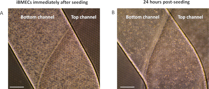
- Cover the chip and transfer it to the microscope to observe seeding density. The bottom channel should be filled with no observable gaps between cells when observed at 4x or 10x under a microscope (Figure 3).
- If seeding density is below 90% coverage or is unevenly distributed, adjust cell density accordingly and repeat steps 7.2–7.6 until the correct density is achieved within the channel. After confirming the correct cell density (Figure 3), seed cells in the remaining chips. To attach cells onto the porous membrane, which is located on the top of the bottom channel, invert each chip and rest in a chip cradle.
- Place a small reservoir (15 mL conical tube cap containing sterile DPBS) inside the 150 mm dish to provide humidity for the cells. Incubate chips at 37 °C for approximately 3 h, or until cells in the bottom channel have attached. Once iBMECs have attached (~3 h post-seeding), flip the chips back to an upright position to allow cell attachment to the bottom portion of the bottom channel.
8. Initiation of flow
- Flow is typically initiated 48 h post-seeding of iBMECs. This time is required for the iBMECs to attach firmly to the chip.
- To maintain laminar flow through the chip, it is important to degas and equilibrate the temperature of the medium. Medium must be pre-warmed in a 37 °C water bath for 1 h.
- Up to 50 mL of warmed medium can be degassed by incubation under a vacuum-driven filtration system for 15 min.
- Priming of portable modules
- Sanitize the exterior of the portable module packaging and trays with 70% ethanol, wipe, and transfer to the BSC. Open the package and place the modules into the tray. Orient them with the reservoirs toward the back of the tray.
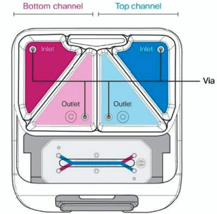
- Pipette 3 mL of pre-equilibrated, warm media to each inlet reservoir. Add EC culture medium to the inlet reservoir of the bottom channel and NDM to the top channel inlet reservoir of the top channel (Figure 4).
- Pipette 300 μL of pre-equilibrated, warm media to each outlet reservoir, directly over each outlet port (Figure 4).
- Place up to six portable modules on each tray. Bring the trays to the incubator and slide them completely into the culture module with the tray handle facing outward.
- Select and run the "Prime" cycle on the culture module. Close the incubator door and allow the culture module to prime the portable modules (takes ~1 min). The priming cycle is completed when the status bar reads "Ready". Remove the tray from the culture module and bring it to the BSC.
- Verify that the portable modules were successfully primed by inspecting the underside of each portable module in the BSC. Look for the presence of small droplets at all four ports.
- If any portable module does not show droplets, rerun the prime cycle on those modules. If any media dripped onto the tray (this may occur more often by the outlet ports), clean tray with 70% ethanol.
- Connection of chips to portable modules, regulation, and initiation of flow
- Gently wash both channels of each chip with warm, equilibrated cell-specific culture medium to remove any possible bubbles in the channel and place small droplets of media (according to the media in the channel) on the top of each inlet and outlet port.
- Insert chips with carriers into the portable modules and place up to six on each tray. Insert trays into the culture module. Program the appropriate organ chip culture conditions (flow rate and stretch) on the culture module.
- Programmed conditions will start as soon as the "Regulate" cycle is complete.
NOTE: The flow rates for each channel can be controlled independently and can be set to rates that range from 0–1,000 µL/h. The BBB chip is typically cultured at 30 µL/h. When flowing media such as EC media or ESM at 30 µL/h and 1000 µL/h, the shear forces are 0.01 dyn/cm2 and 0.33 dyn/cm2, respectively. - Run the "Regulate" cycle, which takes approximately 2 h, after which the culture module will begin flow at the preset organ chip culture conditions.
Representative Results

Figure 1: Schematic of the top view of the chip in the chip carrier, with labeled ports.

Figure 2: Flowchart of the iPSC-based BBB chip preparation and workflow. Pre-differentiation of both neural and endothelial cells from iPSCs is required before initiation of the workflow.

Figure 3: Seeding of iBMECs in the bottom channel. Brightfield images of iBMECs seeded in the bottom channel (A) immediately after seeding or (B) 24 h post-seeding, after cells have attached.

Figure 4: Schematic of the connected chip and portable module with labeled inlet and outlet media reservoirs.
Disclosures
The authors have nothing to disclose.
Materials
| Accutase | EMD Millipore | SCR005 | Dissociation solution |
| B27 | Gibco | 12587010 | |
| Bfgf | Peprotech | 100-18B | |
| Chip-S1 | Emulate Inc | Chip-S1 | Organ-Chip |
| Collagen IV | Sigma | C5533 | |
| DMEM: F12 | Thermo Fisher Scientific | 31330038 | |
| Emulate Reagent 1 (ER-1) | Emulate Inc | ER-1 | |
| Emulate Reagent 2 (ER-2) | Emulate Inc | ER-2 | |
| Fibronectin | Sigma | F1141 | |
| Glutamax | Life Technologies | 35050038 | Glutamine supplement |
| hBDNF | Peprotech | 450-02 | |
| KOSR | Thermo Fisher Scientific | 10828028 | |
| Laminin | Sigma | L2020 | |
| Matrigel | Corning | 354234 | Basement membrane matrix |
| mTeSR1 | StemCell Technologies, Inc. | 85851 | |
| NEAA | Biological industries | 01-340-1B | |
| NutriStem | Biological industries | 05-100-1A | Alternate media |
| Platelet-poor plasma-derived bovine serum (PPP) | Biomedical Technologies | J64483AB | |
| Retinoic acid (RA) | Sigma | R2625 | |
| Steriflip-GP Sterile Centrifuge Tube Top Filter Unit | Millipore | SCGP00525 | |
| β-mercaptoethanol | Life Technologies | 31350010 |

