Optimization, Test and Diagnostics of Miniaturized Hall Thrusters
Summary
Here, we present a protocol to test and optimize space propulsion systems based on miniaturized Hall-type thrusters.
Abstract
Miniaturized spacecraft and satellites require smart, highly efficient and durable low-thrust thrusters, capable of extended, reliable operation without attendance and adjustment. Thermochemical thrusters which utilize thermodynamic properties of gases as a means of acceleration have physical limitations on their exhaust gas velocity, resulting in low efficiency. Moreover, these engines demonstrate extremely low efficiency at small thrusts and may be unsuitable for continuously operating systems which provide real-time adaptive control of the spacecraft orientation, velocity and position. In contrast, electric propulsion systems which use electromagnetic fields to accelerate ionized gases (i.e., plasmas) do not have any physical limitation in terms of exhaust velocity, allowing virtually any mass efficiency and specific impulse. Low-thrust Hall thrusters have a lifetime of several thousand hours. Their discharge voltage ranges between 100 and 300 V, operating at a nominal power of <1 kW. They vary from 20 to 100 mm in size. Large Hall thrusters can provide fractions of millinewton of thrust. Over the past few decades, there has been an increasing interest in small mass, low power, and high efficiency propulsion systems to drive satellites of 50-200 kg. In this work, we will demonstrate how to build, test, and optimize a small (30 mm) Hall thruster capable of propelling a small satellite weighing about 50 kg. We will show the thruster operating in a large space environment simulator, and describe how thrust is measured and electric parameters, including plasma characteristics, are collected and processed to assess key thruster parameters. We will also demonstrate how the thruster is optimized to make it one of the most efficient small thrusters ever built. We will also address challenges and opportunities presented by new thruster materials.
Introduction
Renewed interest in the space industry has in part been catalyzed by highly efficient electric propulsion systems that deliver enhanced mission capabilities at increasingly reduced launch costs1,2,3. Many different types of space electric propulsion devices have recently been proposed and tested4,5,6,7,8 supported by the present-day interest in space exploration9,10. Among them, gridded ion11,12 and Hall-type thrusters13,14 are of primary interest due to their ability to reach very high efficiency of about 80%, exceeding that of any chemical thruster, including the most efficient oxygen-hydrogen systems, the efficiency of which is limited to about 5000 m/s by the principal physical laws15,16,17,18.
Comprehensive, reliable testing of miniaturized space thrusters typically requires a large complex of test facilities that include test chambers, vacuum facilities (pumps), control and diagnostics instruments, a system for measurement of plasma parameters19, and a wide range of auxiliary equipment that sustain the operation of the thruster, such as an electric power supply system, propellant supply unit, thrust measurement stand and many others20,21. Moreover, a typical space propulsion thruster consists of several units which separately influence the efficiency and service life of the whole thrust system, and therefore, could be tested both separately and as part of the thruster assembly22,23. This significantly complicates test procedures and implies long test periods24,25. Reliability of a thruster's cathode unit, as well as operation of thrusters when different propellants are used also requires special consideration26,27.
To quantify performance of an electric propulsion system, and to qualify modules for operational deployment in space missions, ground testing facilities which enable simulation of realistic space environments are needed for testing of multi-scaled propulsion units28,29,30. An example of such a system is a large scaled space environment simulation chamber located at the Space Propulsion Centre-Singapore (SPC-S, Figure 1a,b)31. When developing such a simulation environment, the following primary and secondary considerations need to be taken into account. Primary concerns are that the thus-created space environment must accurately and reliably simulate a realistic space environment, and the in-built diagnostic systems must provide precise and accurate diagnostics during performance evaluation of a system. Secondary concerns are that the simulated space environments must be highly customizable to enable rapid installation and testing of different propulsion and diagnostic modules, and the environment must be able to accommodate high throughput testing to optimize discharge and operational conditions of multiple units simultaneously.
Space environment simulators and pumping facilities
Here, we illustrate two simulation facilities at SPC-S that have been implemented for the testing of miniaturized electric propulsion systems, as well as integrated modules. These two facilities are of different scales, and primarily have different roles in the process of performance evaluation, as outlined below.
Large plasma space actuation chamber (PSAC)
The PSAC has dimensions of 4.75 m (Length) x 2.3 m (Diameter) and has a vacuum pumping suite which comprises of numerous high capacity pumps working in tandem. It is able to achieve a base pressure lower than 10-6 Pa. It has an integrated vacuum control readout and pump activation/purge system for evacuation and purging of the chamber. It is equipped with numerous customizable flanges, electrical feedthroughs and visual diagnostic portholes to provide line test facility. This, together with a full-suite of diagnostics capabilities mounted internally, allows it to be rapidly modified for multi-modal diagnostics. The scale of PSAC also allows for testing of completely integrated modules for applications in a simulated environment.
PSAC is the SPC-S flagship space environment simulation facility (Figure 1c,d). Its sheer size allows for testing of complete modules of up to a few U's mounted on a quadfilar stage. The advantage of this method would be in the real-time visualization of how the propulsion modules as mounted on different payloads may influence in situ maneuvering of payloads in space. This is simulated through the mounting and suspension of the entire payload on a proprietary quadfilar thrust measurement platform. The thruster can then be fired, and the suspended platform with the thruster and payload would be tested according to space conditions. Propellant gas feedstocks which enter the test environment via the electric propulsion modules are pumped out efficiently by the vacuum suite to ensure that the chamber's overall pressure is not altered, thus, maintaining a realistic space environment32,33,34. Furthermore, electric propulsion systems typically involve the production of plasmas and exploit the manipulation of trajectories of charged particles exiting the system in order to generate thrust35. In smaller simulation environments, the buildup of charge or plasma sheaths on the wall may affect the discharge performance through plasma-wall interactions due to its proximity to the propulsion system, especially for micropropulsion where typical thrust values are in the order of millinewtons. Therefore, special attention and emphasis must be made to account for and marginalize contributions from such factors36. The PSAC's large size minimizes plasma-wall interactions, rendering them negligible, giving a more accurate representation of discharge parameters and enabling monitoring of plume profiles in electric propulsion modules. The PSAC is typically used in full module evaluation and systems integration/optimization processes which allows for quick translation of thruster prototypes into operationally ready systems for ground testing in preparation for space qualification.
Scaled plasma space environment simulator (PSEC)
The PSEC has dimensions of 65 cm x 40 cm x 100 cm and has a vacuum pumping suite which comprises of six high capacity pumps working in tandem (dry vacuum pump, turbomolecular and cryo vacuum pumps). It is able to achieve a base pressure lower than 10-5 Pa when the whole pumping system is operating (all pumps are in use). Pressure and propellant flows are monitored in real-time through integrated mass flow readout boxes and pressure gauges. The PSEC is primarily employed in endurance testing of thrusters. Thrusters are fired for extended periods of time to evaluate effects of plasma damage on discharge channels and on its lifetime. Additionally, as shown in Figure 2, a complex gas flow controller network in this facility enables quick connection of other feedstock propellants to the cathode and anodes to test compatibility of thrusters with novel propellants and effects of the latter on thruster performance. This is of increased interest to research groups working on "air-breathing" electric thrusters utilizing novel propellants during operation.
Integrated diagnostic facilities (multi-modal diagnostics)
Different integrated diagnostic facilities, equipped with automated integrated robotic systems (AIRS-µS)19,23, have been developed for the two systems in PSEC and PSAC to cater for diagnostics at different scales and purposes.
Integrated diagnostics in PSEC
The diagnostic tools in PSEC essentially hinge on real-time monitoring of discharge through extended operations. The quality management system monitors residual gas in the facility for contaminant species that arise from sputtering of material during a discharge. These trace amounts are quantitatively monitored over time to evaluate erosion rates of the discharge channel and electrodes of the thruster to estimate the thruster's lifetime. The optical emissions spectrometer (OES) complements this procedure by monitoring spectral lines corresponding to electronic transitions of contaminant species due to erosion, such as copper from the electronics. OES also enables non-invasive plasma diagnostics and active monitoring of plume profile which qualitatively evaluates performance of the thruster. Finally, a robotic Faraday probe which can be controlled remotely, or set to fully autonomous mode, is used to derive quick sweeps of the plume profile to optimize collimation of beam through parametrically varying discharge conditions (Figure 3).
Integrated diagnostics in PSAC
The luxury of physical space in the PSAC enables installation of multiple thruster systems at various locations due to its modular design, allowing for plug-and-play-like installation for various diagnostics simultaneously. Figure 4 shows the internal cross-section of the PSAC in various configurations, with the fully suspended quadfilar thrust measurement platform being its most notable and permanent fixture. Turret systems, controlled autonomously or wirelessly via Android apps using microcontrollers and Bluetooth modules, can then be mounted in a modular manner facing the thruster to obtain characteristics of the plume through the installation of various probes such as Faraday, Langmuir and Retarding Potential Analyzer (RPA). Also shown in Figure 4 is the ability of the PSAC to allow for configurable mounting of thruster systems for rapid simultaneous diagnostics of various plasma parameters. The thrusters can be mounted vertically in a single column and tested rapidly, one after another to avoid interactions between the different thruster systems. It has been verified that efficient evaluation of up to 3 different modules at a single instance is possible, thus significantly reducing the downtime during evacuation and purging processes required otherwise when testing systems individually. On the other hand, this system is a valuable opportunity for testing the thruster assemblies that should operate in a bunch, on the same satellite. The thrusters can be mounted vertically in a single column and tested rapidly, one after another to avoid interactions between the different thruster systems. It has been tested to be effective in the evaluation of up to 3 different modules at a single instance, significantly reducing downtime during evacuation and purging processes required otherwise when testing systems individually.
It is vital to determine the thrust in micropropulsion systems accurately so that parameters such as efficiency, ηeff and the specific impulse Isp, are accurate, thus, giving a reliable representation of the dependence of thruster performance on various input parameters such as the propellant flow, and power supplied to the different terminals of the thrusters as shown in Equations 1 and 2. Explicitly, performance evaluation of micropropulsion systems typically revolves around the measurement of thrust generated from the system at various operating parameters. Therefore, performance evaluation systems need to be calibrated according to a set of standards before being installed into the space environment for use in diagnostics and testing to ensure their reliability and accuracy19.


Typical systems employ force calibration externally before thrust measurement units are installed into the test environment38. However, such systems do not account for the space environments affecting the material properties of the calibration standards, and for electrical, vacuum and thermal influences on the degradation of the calibrated standards over the dynamic course of performance evaluation of the thrusters. The automated wireless calibration unit shown in Figure 5, on the other hand, allows for in situ calibration of the system in the simulated environment before the thruster is operational. This accounts for the dynamic effects of the test environment on the measurement stage, and allows for rapid re-calibration of the system prior to firing of thrusters. The system also features a symmetric modular null thrust verification unit which verifies the thrust independently. It is operated while the thruster is operational for in situ analysis of the derived thrusts from given discharge conditions. The entire process is done via MATLAB apps, allowing users to focus on optimization of hardware and design of propulsion systems, and expedites testing of such systems. Details of this method would be elaborated in the following subsection.
Protocol
Here we present the protocols for the thrust calibration procedure and performance evaluation, independent thrust verification via null measurement and plume profilometry through spatial in situ data sensing.
1. Thrust calibration procedure and thrust performance evaluation
- Ensure that all components are installed in the chamber as shown in Figure 5.
- Test the connectivity of the diagnostic tools externally before sealing the chamber.
- Use the integrated facility control to seal the chamber.
- Turn on the vacuum pumps in cascading order starting from the dry pumps (until the chamber reaches 1 Pa), turbo-molecular pumps (until it reaches ~5 x 10⁻⁴ Pa), and then the cryogenic pumps.
NOTE: PSAC is left to pump down to high vacuum (< ~10-5 Pa) to simulate space environment. The protocol can be paused here. - Use the developed apps to synchronize the devices with the wireless transponder in the chamber. The synchronization process is complete when the light-emitting diode (LED) on the transponder stops flashing.
- Once the desired vacuum has been obtained, take an initial reading (analog voltage) off the laser displacement sensor as a baseline.
- Use the developed app to trigger the lowering of a weight (of a precisely known and calibrated mass of copper loop) for force translation on the quadfilar stage.
NOTE: The mass of each copper loop depends on the intended sensitivity of the quadfilar stage being used. In this case, the mass of each copper loop was in the order of 100 mg for the extended calibration regime and 10 mg for the fine calibration regime. See the representative results for more information. - Record the displacement (analog voltage) from the laser displacement sensor when it is triggered after the mass is fully lowered and its weight is translated into a horizontal force.
- Repeat the process (steps 1.7 and 1.8) of lowering the weights and recording of the displacement of the quadfilar stage until all the calibrations weights are expanded. All the weights will be automatically returned to the equilibrium position by the calibration unit after the sequence is completed to allow the quadfilar stage to reach an equilibrium position before thruster can be fired. Save the calibration factor ( File | Save as | "Factor.txt").
- Draw a calibration curve to obtain the calibration factor for the system installed on the quadfilar stage, where the calibration factor (in mN/V) is the gradient of the force/voltage graph.
- Record a baseline analog voltage from the laser displacement sensor again before firing the thruster.
- Activate the in situ MATLAB program for calculating thrust instantaneously using Equation 3 (see the representative results) and input the calibration factor derived in step 1.9 ( File | Open | "Factor.txt").
- The thrusters can then be fired again. Capture the desired parameters in real time using the in-house data acquisition program.
NOTE: Alternatively, an integrated app can be used to fully automate the calibration process while synchronizing the actuation sequence from the motors, and data acquisition from the sensors accordingly.
2. Null measurement protocol for independent thrust verification
- First, take a baseline (analog voltage) reading (from the laser displacement sensor) of the thruster in equilibrium position.
- Toggle operational parameters to desired values from the thruster control panel and fire the thruster.
- Once the thruster is fired, wait for the oscillations on the quadfilar pendulum to stabilize.
- After the quadfilar stabilizes to a steady state, use the control app for the null measurement system to trigger the lowering of weights. Readings from the laser displacement sensor are monitored simultaneously. The weights are continually lowered until the quadfilar stage is actuated back into equilibrium.
- Once the equilibrium position is reached, terminate the actuation sequence, and determine the force required to bring the quadfilar system back to equilibrium.
- Trigger a stopper block to stop the quadfilar stage from moving.
- Compute mass corresponding to the horizontal force required to pull the system back into equilibrium.
3. Actuation of robotic turrets for spatial in situ data sensing and plume profilometry
NOTE: During operation of the thruster, an operator may choose to actuate the system manually to desired angles to obtain plume characteristics at particular locations or trigger an automated sequence.
- Mount the thruster on a moving stage (as in the case of PSAC) before starting the experiment.
- Activate the stop-bar mechanism to prevent the stage from actuating during the experiment.
- Trigger the measurement protocol and servo motor to actuate the probe to the 0° position.
- Acquire a measurement from the probe.
NOTE: Depending on the type of probes installed, the measurement processes can be varied according to the programmable sequence for obtaining complete spatial plume profiles of the discharge. (a) If a Faraday probe is mounted, a reading off a source meter is taken (where a bias of -30 V is continuously applied to the guard rings). (b) If a Langmuir probe is mounted, a sawtooth voltage waveform is supplied to the probe and the I-V characteristics are obtained and interpreted. (c) If an RPA is mounted, a sawtooth voltage waveform is applied to the discriminating grid, and the I-V characteristics are obtained and interpreted. - Trigger the servo motor using the microcontroller, to move to the next angular position where the probe sequence is triggered to make a measurement again.
- Save the measurements in individually marked arrays in a data matrix.
- Repeat steps 3.5 and 3.6 until a full sweep up to 180° has been performed, and the probe is brought back to 0°.
- Analyze the saved data.
Representative Results
Thrust calibration procedure and thrust performance evaluation
Evaluation of thrust values from the quadfilar thrust measurement stage comes in two phases. The first phase is through obtaining calibration factors from the automated wireless calibration unit shown to the right of Figure 5. In this calibration process, fine weights are lowered across a smooth polytetrafluoroethylene bar which translates the vertical effects of a weight into a horizontal force as attached to the thruster on the quadfilar stage. A high-resolution laser displacement sensor then measures the displacement at each interval accordingly. This is monitored by an operator via a data acquisition app as shown in Figure 6, and a calibration factor is obtained at the end of the series where numerous calibrated weights are lowered onto the system. The calibration factor S is obtained from the best fit line of the horizontal force-displacement graph, and the subsequent thrust is calculated using Equation 3:

where Vbaseline is the analog baseline voltage from the laser displacement sensor read prior to firing the thruster, and Vmeasured is the measured voltage from the sensor during in situ operation of the thruster.
A clearer representation of the calibration system is shown in Figure 7. It is to be noted that the green line and red circles are for illustration purposes only and merely serve as a guide for the eye. In reality, the green line is a fine Madeira polyamide fiber which connects to the mounted thruster. The calibrated weights are small copper loops that have been carefully weighed by a high precision mass balance, and they can be adjusted accordingly to allow for a fine calibration regime initially (with smaller intervals in difference between masses), and to an extended regime (where larger masses are added towards the end of the calibration sequence).
A typical force-voltage graph will produce a straight line as shown in Figure 8 when the calibration unit, laser displacement sensor and quadfilar platform are properly installed. In this case, the plot yields a calibration factor (gradient) of 27.65 mN∙V-1 in a standardized set up for thrust measurements over a wide range of forces.
The calibration factor can be altered by modifying the sensitivity of the quadfilar platform, which depends on several factors such as the length of the quadfilar wires. In Figure 8, the sensitivity of the setup has been modified to fit in calibration weights for extended regimes. Both fine and coarse calibration weights are included to yield a calibration plot that is linear in both regimes.
A sample of the in situ measurements for thrust measured is shown in Figure 9. In this case, it shows how an operator is able to monitor the dependence of thrust on discharge voltage during the course of the experiment until the discharge is extinguished. Effects of other input parameters on the thrust can also be monitored in the same manner.
Using the quadfilar thrust measurement stage, we were able to measure the thrust generated by our hall thruster at various input powers, given by the discharge current and applied voltage. Through this information, the variation of  and
and  with respect to input power can be obtained. Figure 10a,b shows how the thrust and vary with input power at 4 different mass flow rates. Finally, the efficiency is plotted against the input power at different mass flow rates in Figure 10c. The results show that our thruster has been optimized to work at input powers below 100 W, where low flow rates have resulted in efficiencies of almost 30%19. Prior to optimization, the thruster barely achieved 20% efficiency at 83 W and 5.5 sccm. The results show that our thruster has been optimized to work at input powers below 100 W, where low flow rates have resulted in efficiencies of almost 30%19. This is arguably a decent achievement compared to the SPT100 Hall thruster, whose efficiency varies between 30% to 40%, and other Hall thrusters of similar sizes and input powers. Figure 10d illustrates the automatically plotted profile of ion current density.
Null measurement protocol for independent thrust verification
While the thruster is being fired, the polyamide wire on the right-hand side corresponding to the calibration unit end is left slack. During the in situ operation of the thruster, the symmetric null measurement verification unit can then be triggered. The symmetric null measurement unit operates in a similar manner to the robotic calibration system shown in Figure 5; the miniature calibration weights attached to a fine polyamide wire are lowered in the system and create a horizontal force applied to the propulsion system. In this case, the horizontal force is applied to pull the quadfilar system which has been displaced upon operation of the thruster back to equilibrium. This process is shown in the time-dependent schematic of the process evolution in Figure 11. The thruster is first fired at t = 0 s, corresponding to panel (a) in the series. The quadfilar stage then displaces to the right as a result of the horizontal force from the propulsion unit. Since the environment is darkened in the space simulator, the motion of the stage is seen as the apparent movement of the thruster in (b). The quadfilar stage then stops oscillating and reaches an equilibrium steady state displacement as shown in (c). At this instance, the null system is triggered and the stepper motor is activated to pull the quadfilar stage back to equilibrium as shown in (d). The stepper motor is triggered to a point where the laser displacement sensor detects that the stage is back in the equilibrium position and the actuation is stopped. A measurement is then taken, and the thrust value from this system is given accordingly.
Actuation of robotic turrets for spatial in situ data sensing and plume profilometry
Modular robotic turret systems are also installed in both PSAC and PSEC for customizable diagnostics of plume profiles. These robotic turrets are also mounted on motor actuated stages for proper probe positioning according to the axial centerline of the thrusters externally. The robotic turrets comprise of shielded stainless steel enclosures containing programmable microcontrollers attached to wireless transponders for receiving and transmitting data. This also allows users to control the movement of the probe externally, while receiving data from sensors without additional electrical connections to the system. It is also worth noting that the modular design of the micro-servo motor actuated turret allows quick refinement of measurement setup that allows for multiple probe arrays including Langmuir, Faraday probe and RPAs be mounted on the same set up according to operational demands at the point of time. Figure 12 shows a schematic illustration of the experimental setup for plume profilometry.
During operation of the thruster, an operator can choose to manually actuate the system to desired angles as illustrated in Figure 12 to obtain plume characteristics at particular locations, or an automated sequence can be triggered. Depending on which probes are installed, the measurement processes can be varied according to the programmable sequence for obtaining complete spatial plume profiles of the discharge.
Such a sequence allows for quick spatial visualization of the plume profile which helps optimize engineering and process optimization in allowing for beam collimation for efficient thruster operation. Actuated turrets and programmable sensing systems allow for autonomous acquisition of plume characteristics at each point, where plasma parameters may be derived and calculated through programmable systems. This may expedite testing of such systems with easy analysis and manipulation of large amounts of data through simple robotic and actuated autonomous systems. In Figure 10d, for example, the plasma parameter being analyzed here is the ion current density at different angular positions. It shows how the discharge power influences the magnitude of the peak ion current density and the full-width at half maxima accordingly. These results show that higher discharge voltages do not necessarily translate to better thruster performance. Here, higher power results in the widening of the plume profile which is an undesirable characteristic of a thruster. This means that some of the exhaust particles have velocities which are not perpendicular to the thruster exit plane, resulting in a thrust in an unintended direction and making precise maneuvers challenging. Moreover, the charges from the plume may damage the payload or other subsystems on the spacecraft. To optimize the thruster to produce a more collimated plume, the current supplied to the magnetic coils and the potential drop at the anode can be adjusted until a satisfactory full-width at half maxima (FWHM) value has been achieved. Prior to plume profile optimization, its FWHM was 33.1° at 140 W but after optimization, it reduced to 23.7° at 110 W. This implies that the plume is now more collimated.
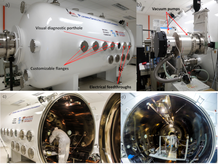
Figure 1: Large space environment facility for testing of electric propulsion thrusters. This flagship facility is located at the Space Propulsion Centre Singapore, National Institute of Education, Nanyang Technological University. (a) Side view of the chamber illustrates transparent portholes for visual diagnostics of test systems, and the multiple vacuum grade electrical feed-throughs that allow for communication, control and diagnostics of systems under test. (b) Vacuum pumps. (c) Side view of the chamber with a side loading hatch open. (d) View of the space simulation chamber with an operator installing diagnostic systems. Reprinted with permission from J. Lim et al., IEEE Trans. Plasma Sci. 46, 338 (2018) and J. Lim et al., IEEE Trans. Plasma Sci. 46, 345 (2018). Copyright 2018 IEEE. Please click here to view a larger version of this figure.
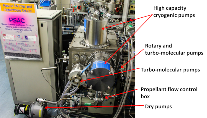
Figure 2: Rear view of a scaled plasma space environment simulator (PSEC). PSEC comprises a total of 6 pumps including high capacity cryogenic pumps, turbo-molecular pumps, and dry pumps. The setup also contains integrated thruster diagnostics. Please click here to view a larger version of this figure.
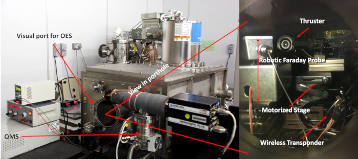
Figure 3: Overview of a plasma diagnostics suite in the PSEC. Right hand side of the figure illustrates a magnified view of the systems as viewed from the porthole from the front of the chamber. The visual diagnostic port also serves as an avenue for optical emission spectroscopy (OES) to be done. As shown in the exterior view of the chamber, a quadropole mass spectrometer is outfitted for residual gas analysis to evaluate material erosion rates due to sputtering in the chamber during prolonged thruster operation. Additionally, wirelessly controlled robotic Faraday probes are also mounted internally to evaluate plume profiles of the thrusters undergoing performance evaluation. Please click here to view a larger version of this figure.

Figure 4: Overview of the integrated plasma diagnostics suite in the PSAC. (a) Customizable design shows a robotic Faraday probe turret placed alongside a quadfilar thrust performance evaluation stage, and an in-situ weight calibration unit. (b) Customizable features allow for up to three different thrusters to be mounted and tested simultaneously, reducing operational downtime and maximizing research output. Please click here to view a larger version of this figure.
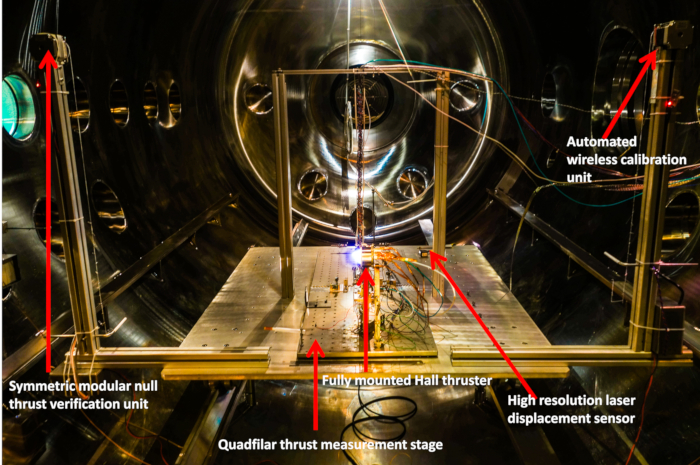
Figure 5: Schematic layout of the symmetric modular null thrust verification unit. Unlike the calibration system, the null thrust verification unit is operated while the thruster is fired to allow for independent verification of the thrust values obtained. Please click here to view a larger version of this figure.

Figure 6: Data acquisition app user interface. The user interface of the MATLAB-based app allows the operator to monitor the thrust and voltage reading from the laser displacement sensor in real time. Please click here to view a larger version of this figure.
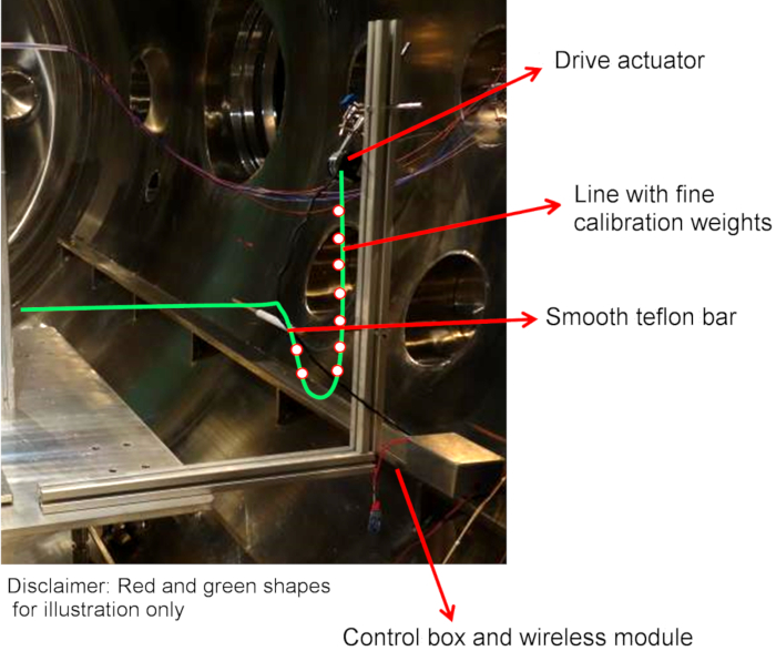
Figure 7: Calibration unit. A robotic calibration unit can be operated by a wireless operator input, or through fully autonomous calibration sequences for quick calibration of a quadfilar system. Design considerations: Minimize external influence; use thin, light weight string and millinewton weights; use low static coefficient bar; line must be flexible enough to produce "u-loop". For the calibration stand, use wireless control unit, fine Madeira monofilament polyamide (nylon) fiber (about 4.0 µm), small copper loops as weights and a smooth polytetrafluoroethylene bar. Line should be attached to rear of mounted thruster on quadfilar pendulum or in line with the center of the reflector plate. Please click here to view a larger version of this figure.
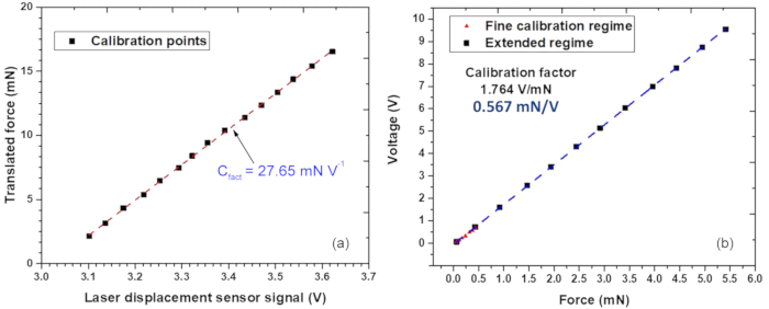
Figure 8: Typical force-voltage and force-voltage graphs for modified setup. (a) Force-voltage graph.The amount of weight which has been lowered and translated into a horizontal force is plotted against the corresponding voltage reading on the laser displacement sensor. The calibration factor (in mN/V) is the gradient of the force/voltage graph which will be used in the data acquisition app. (b) Force/voltage graph. The sensitivity of the setup towards the applied force was increased to accommodate for both fine and coarse calibration. Please click here to view a larger version of this figure.
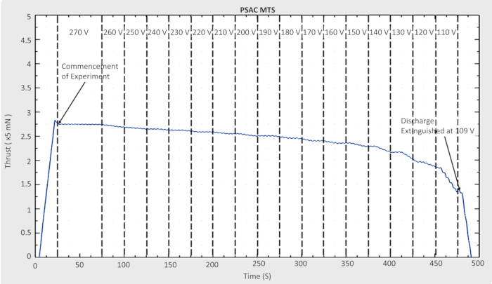
Figure 9: In-situ performance evaluation. Another software program allows the thrust performance to be monitored in real-time when an input parameter, the discharge voltage in this case, is changed gradually. Please click here to view a larger version of this figure.
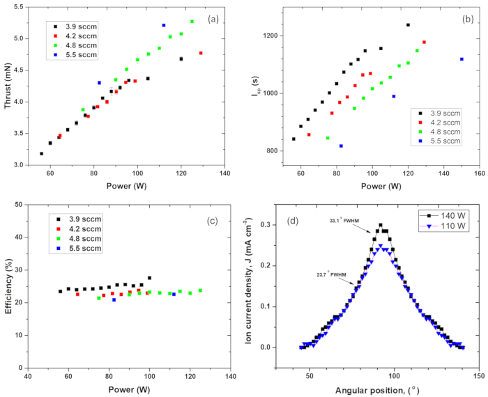
Figure 10: Evaluation of thruster characteristics. (a, b) Thrust and specific pulse as functions of input power at four different mass flow rates. (c) Efficiency plotted against the input power at different mass flow rates. (d) The automatically plotted profile of ion current density. Please click here to view a larger version of this figure.
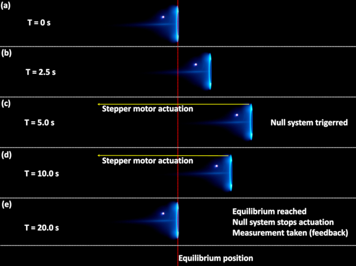
Figure 11: Time evolution of the null thrust verification unit in operation during firing of a Hall thruster at SPC-S. (a) t = 0 s, where the Hall thruster is first fired and moves away from the equilibrium position. (b) Quadfilar stage displaces to the right as shown by the relative motion of the Hall thruster. (c) Quadfilar stage stops oscillating and reaches an equilibrium steady-state position. Null system is triggered and the stepper motor actuation commences. (d) Null system is triggered to slowly pull the thruster mounted on the quadfilar stage back to equilibrium. (e) Thruster reaches an equilibrium position. Null measurement unit stops the stepper motor actuation. Measurement is taken. Please click here to view a larger version of this figure.
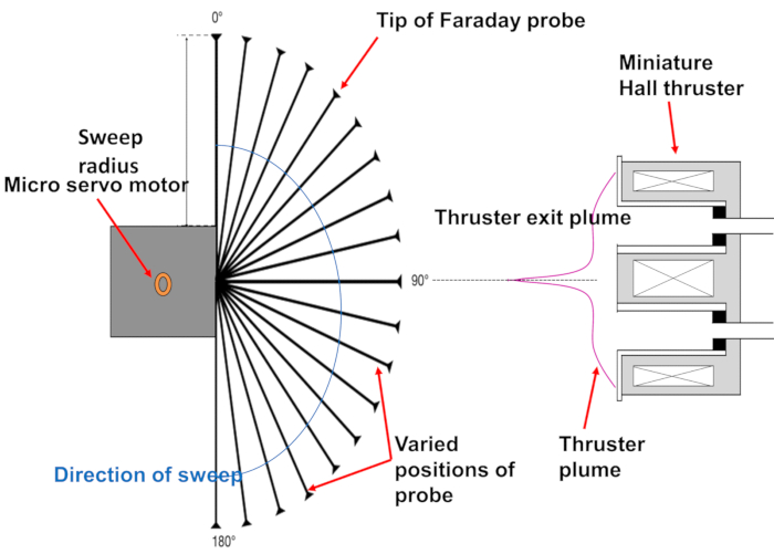
Figure 12: Schematic representation of the actuation of the modular multi-probe turret. The entire system is controlled wirelessly, and Faraday probe can be replaced quickly through snapping on a different probe module. Connections are made through BNC-type adapters for easy twist-on conversion and installation. Please click here to view a larger version of this figure.

Figure 13: Schematics of a Hall-type thruster. Similar setups with varied configurations based on a generalized layout presented in this figure have also been employed by other groups. Please click here to view a larger version of this figure.
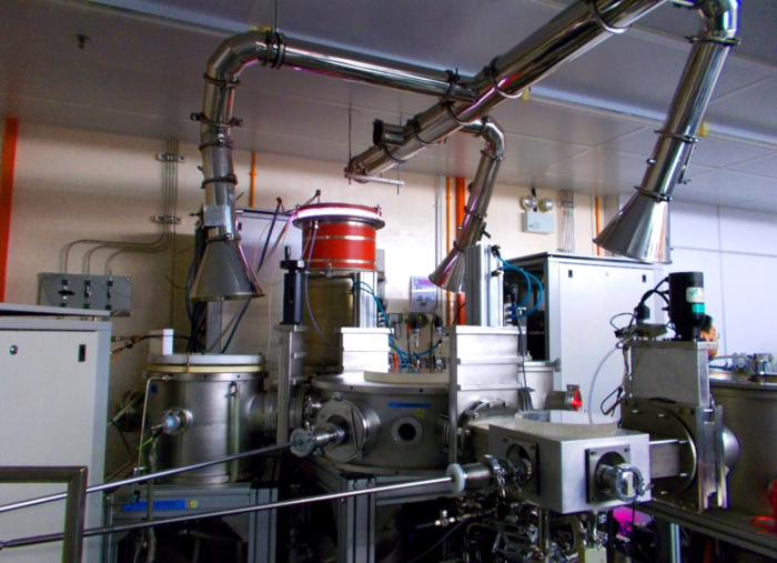
Figure 14: Inductively Coupled Plasma Facility for synthesis of novel materials at the Plasma Sources Application Centre / Space Propulsion Centre, Singapore. A powerful plasma system enables synthesis of silicon-based materials for innovative, highly efficient solar cells, as well as boron nitride and other nanostructured materials for applications in the modern miniaturized thrusters. Please click here to view a larger version of this figure.
Discussion
Typical Hall-type thrusters44 are relatively simple, cheap and highly efficient devices that could accelerate an ion flux to the velocities of several tens of km/s, providing thrust required for accelerating satellites and spacecraft, as well as for maneuvering, orientation, position and attitude control, and de-orbiting at the end of their operation service life. Application of Hall thrusters on satellites and other orbital payloads enhance mission lifetime, allow orbital transfer and formation/constellation flying of multiple satellites, and enable multi-mission capabilities. Structurally (see schematics in Figure 13), a Hall thruster is a coaxial chamber with an anode installed at one side, and a cathode placed near the exit. Easily ionized but relatively heavy, Xe gas, is usually used as a propellant, yet other elements such as iodine could be used in some cases45. An ion flux is accelerated by an electrostatic field that is set between the anode and cathode, while a magnetic field created by a set of coils or a system of permanent magnets ensures an electron drift current around the central part of the chamber46. This electron drift current ensures efficient ionization of a neutral gas and simultaneously, it provides compensation of a positive ion change.
The efficiency of an electric propulsion thruster depends significantly on its design, especially the shape and configuration of electrodes and parameters of the magnetic field, and materials used for the accelerating channel, anode and emissive inserts in the cathode. For example, the magnetic field topology of the thruster can be configured in such a way that the location of maximum magnetic field strength and hence, the ionization zone are pushed further downstream, near the channel outlet, thus, reducing the interaction between high energy ions and the channel wall47. This in turn reduces erosion rates of the channel wall and its dependence on wall material properties, making wall material replacement more feasible. The lifetime of Hall-type thrusters depends highly upon the materials used for its components, especially the ones that are in contact with the plasma. Going forward, novel materials, as well as equipment and techniques for its synthesis and testing48,49 are needed to further improve the lifetime of Hall-type thrusters.
Novel materials are synthesized in the PSAC/SPCS labs using mainly a powerful, highly adaptive, efficient inductively coupled plasma facility (Figure 14)50,51. A spectrum of novel materials includes, but is not limited to silicon-based wafers for innovative, highly efficient solar cells, as well as boron nitride, graphene-containing nanostructures52,53, metamaterials54,55 and other nanostructured materials for applications in modern miniaturized thrusters, where they are used for significant intensification and optimization of the key parameters of thrusters56,57. Other available equipment include arc and capacitive-coupled plasma systems for the for advanced plasma treatment of materials58. Indeed, a significant enhancement of thruster parameters could be attained through implementation of sophisticated test, design, materials and simulation optimization techniques59,60. Moreover, applications of novel materials and material systems could ensure efficient approaches towards, e.g., heat transfer61, wear resistance62, and other problems associated with the efficiency and service life of miniaturized space thrusters. Plasma-based material facilities enable synthesis, test and application of the most advanced materials in the thrusters currently being designed63. Indeed, it has already been demonstrated that plasma-enabled techniques which involve highly energetic fluxes on matter and energy, allow for efficient activation of surfaces64,65 and hence, control over self-organization, nucleation66,67,68 and other sophisticated surface-based processes leading to the creation of the most advanced materials69,70,71. Note that carbon-containing materials such as carbon nanowalls, nanotubes and vertically-oriented graphene arrays could be quite promising for the application in the electric propulsion thrusters as electron emitting materials72,73,74 and promising material for the walls of acceleration channels and discharge chambers75.
Plasma-made multilayered, core-shell and porous materials76 could also find applications in various parts of the electric propulsion systems77. Controlled synthesis of metallic single-walled carbon nanotubes78 and plasma-enabled, catalyst-free growth of carbon nanotubes on mechanically-written Si features79 is also possible in the plasma-driven process80.
In summary, we have presented a protocol to test and optimize miniaturized space propulsion systems. Diversified sophisticatedly designed equipment, large vacuum chambers, powerful pumping platforms and various diagnostic complexes were used to perform precise, informative characterization of micro-propulsion thrusters under conditions close to those found in open space. Skilled personnel, adequate simulation and theoretical support are also of key importance to keep the micropropulsion design and technology progressing steadily. Development of novel materials is the second key factor that could ensure significant breakthroughs in improving performance characteristics of modern electric propulsion systems, including small satellites and CubeSats with the whole set of supply systems, peripheral instruments, tools and payload.
Declarações
The authors have nothing to disclose.
Acknowledgements
This work was supported in part by OSTIn-SRP/EDB, the National Research Foundation (Singapore), Academic Research Fund AcRF Tier 1 RP 6/16 (Singapore), and the George Washington Institute for Nanotechnology (USA). I. L. acknowledges the support from the School of Chemistry, Physics and Mechanical Engineering, Science and Engineering Faculty, Queensland University of Technology.
Materials
| Arduino Microcontroller | Arduino | Arduino Uno Rev 3 | |
| Bluetooth communication device | SG Botic | WIR-02471 | |
| Cryogenic Pump | ULVAC | CRYO-U12HLE | |
| Digital Oscilloscope | Yokogawa | DLM 2054 | |
| Dry Pump | Agilent | Triscroll-600 | |
| High resolution laser displacement sensor | Micro-Epsilon | optoNCDT ILD-1420-50 | |
| Mass Flow Controller | MKS | MKS M100B | |
| Optical Emission Spectrometer | Avantes | AvaSpec-ULS2048XL-EVO | |
| Servo Motor | Tower Pro | Servo Motor SG90 | |
| Stepper Motor | Oriental Motor | PKP213D05A | |
| Turbomolecular Pump | Pfeiffer | ATH-500M |
Referências
- Levchenko, I., Keidar, M., Cantrell, J., Wu, Y. L., Kuninaka, H., Bazaka, K., Xu, S. Explore space using swarms of tiny satellites. Nature. 562, 185-187 (2018).
- Kishi, N. Management analysis for the space industry. Space Policy. 39-40, 1-6 (2017).
- Chen, Y. China’s space policy-a historical review. Space Policy. 37, 171-178 (2016).
- Levchenko, I., Bazaka, K., Mazouffre, S., Xu, S. Prospects and physical mechanisms for photonic space propulsion. Nature Photonics. 12, 649-657 (2018).
- Mazouffre, S. Electric propulsion for satellites and spacecraft: established technologies and novel approaches. Plasma Sources Sciency and Technology. 25, 033002 (2016).
- Rafalskyi, D., Aanesland, A. Brief review on plasma propulsion with neutralizer-free systems. Plasma Sources Sciency and Technology. 25, 043001 (2016).
- Levchenko, I., Bazaka, K., Ding, Y., Raitses, Y., Mazouffre, S., Henning, T., Klar, P. J., et al. Space micropropulsion systems for Cubesats and small satellites: from proximate targets to furthermost frontiers. Applied Physics Reviews. 5, 011104 (2018).
- Garrigues, L., Coche, P. Electric propulsion: comparisons between different concepts. Plasma Physics and Controlled Fusion. 53, 124011 (2011).
- Levchenko, I., Xu, S., Mazouffre, S., Keidar, M., Bazaka, K. Mars Colonization: Beyond Getting There. Global Challenges. 2, 1800062 (2018).
- Grimaud, L., Mazouffre, S. Performance comparison between standard and magnetically shielded 200 Hall thrusters with BN-SiO2 and graphite channel walls. Vacuum. 155, 514-523 (2018).
- Choueiri, E. Y. A critical history of electric propulsion: the first 50 years (1906-1956). Journal of Propulsion and Power. 20, 193-203 (2004).
- Ozaki, T., Kasai, Y., Nakagawa, T., Itoh, T., Kajiwara, K., Ikeda, M. In-Orbit Operation of 20 mN Class Xenon Ion Engine for ETS-VIII. , IEPC-2007-084 (2007).
- Ding, Y., Li, H., Li, P., Jia, B., Wei, L., Su, H., Sun, H., Wang, L., Yu, D. Effect of relative position between cathode and magnetic separatrix on the discharge characteristic of hall thrusters. Vacuum. 154, 167-173 (2018).
- Ding, Y., Peng, W., Sun, H., Wei, L., Zeng, M., Wang, F., Yu, D. Performance characteristics of No-Wall-Losses Hall thruster. The European Physical Journal – Special Topics. 226, 2945-2953 (2017).
- Ahedo, E. Plasmas for space propulsion. Plasma Physics and Controlled Fusion. 53, 124037 (2011).
- Charles, C. Plasmas for spacecraft propulsion. Journal of Physics D: Applied Physics. 42, 163001 (2009).
- Ding, Y., Sun, H., Li, P., Wei, L., Su, H., Peng, W., Li, H., Yu, D. Application of hollow anode in Hall thruster with double-peak magnetic fields. Journal of Physics D: Applied Physics. 50, 335201 (2017).
- Conversano, R. W., Goebel, D. M., Mikellides, I. G., Hofer, R. R. Performance analysis of a low-power magnetically shielded Hall thruster: computational modeling. Journal of Propulsion and Power. 33, 992-1001 (2017).
- Chen, F. F. Langmuir probe analysis for high density plasmas. Physics of Plasmas. 8, 3029-3041 (2001).
- Neumann, A. Update on diagnostics for DLR’s electric propulsion test facility. Procceedins of Engineering. 185, 47-52 (2017).
- Snyder, J. S., Baldwin, J., Frieman, J. D., Walker, M. L., Hicks, N. S., Polzin, K. A., Singleton, J. T. Recommended practice for flow control and measurement in electric propulsion testing. Journnal of Propulsion and Power. 33, 556-565 (2017).
- Conversano, R. W., Goebel, D. M., Hofer, R. R., Mikellides, I. G., Wirz, R. E. Performance analysis of a low-power magnetically shielded hall thruster: Experiments. Journal of Propulsion and Power. 33, 975-983 (2017).
- Pottinger, S., Lappas, V., Charles, C., Boswell, R. Performance characterization of a helicon double layer thruster using direct thrust measurements. Journal of Physics D: Applied Physics. 44, 235201 (2011).
- Ding, Y., Peng, W., Sun, H., Wei, L., Zeng, M., Wang, F., Yu, D. Visual evidence of suppressing the ion and electron energy loss on the wall in Hall thrusters. Japanese Journal of Applied Physics. 56, 038001 (2017).
- Ding, Y., Peng, W., Wei, L., Sun, G., Li, H., Yu, D. Computer simulations of Hall thrusters without wall losses designed using two permanent magnetic rings. Journal of Physics D: Applied Physics. 49, 465001 (2016).
- Rovey, J. L., Gallimore, A. D. Dormant cathode erosion in a multiple-cathode gridded ion thruster. Journal of Propulsion and Power. 24, 1361-1368 (2008).
- Linnell, J. A., Gallimore, A. D. Efficiency analysis of a hall thruster operating with krypton and xenon. Journnal of Propulsion and Power. 22, 1402-1412 (2006).
- Funaki, I., Iihara, S., Cho, S., Kubota, K., Watanabe, H., Fuchigami, K., Tashiro, Y. Laboratory Testing of Hall Thrusters for All-electric Propulsion Satellite and Deep Space Explorers. , (2016).
- Ding, Y., Sun, H., Li, P., Wei, L., Xu, Y., Peng, W., Su, H., Yu, D. Influence of hollow anode position on the performance of a Hall-effect thruster with double-peak magnetic field. Vacuum. 143, 251-261 (2017).
- Ding, Y., Peng, W., Sun, H., Xu, Y., Wei, L., Li, H., Zeng, M., Wang, F., Yu, D. Effect of oblique channel on discharge characteristics of 200-W Hall thruster. Physics of Plasmas. 24, 023507 (2017).
- Lim, J. W. M., Huang, S. Y., Xu, L., Yee, J. S., Sim, R. Z., Zhang, Z. L., Levchenko, I., Xu, S. Automated Integrated robotic systems for diagnostics and test of electric and μ-propulsion thrusters. IEEE Transaction of Plasma Sciency. 46, 345-353 (2018).
- Underwood, C., Sergio, P., Lappas, V. J., Bridges, C. P., Baker, J. Using CubeSat/micro-satellite technology to demonstrate the autonomous assembly of a reconfigurable space telescope (AAReST). Acta Atronaut. 114, 112-122 (2015).
- Kamahawi, H., Huang, W., Haag, T. Investigation of the effects of facility background pressure on the performance and voltage-current characteristics of the high voltage hall accelerator. AIAA. , (2014).
- Lim, J. W. M., Huang, S. Y., Sun, Y. F., Xu, L., Sim, R. Z. W., Yee, J. S., Zhang, Z. L., Levchenko, I., Xu, S. Precise calibration of propellant flow for practical applications and testing in Hall thruster setups. IEEE Transaction on Plasma Science. 46, 338-344 (2018).
- Boeuf, J. P. Tutorial: Physics and modeling of Hall thrusters. Journal of Applied Physics. 121, 011101 (2017).
- Ikeda, T., Togawa, K., Tahara, H., Watanabe, Y. Performance characteristics of very low power cylindrical Hall thrusters for the nanosatellite ‘PROITERES-3. Vacuum. 88, 63-69 (2013).
- Jackson, S. W., Marshall, R. Conceptual design of an air-breathing electric thruster for CubeSat applications. J. Spacecraft Rockets. , (2018).
- Rohaizat, M. W. A. B., Lim, M., Xu, L., Huang, S., Levchenko, I., Xu, S. Development and calibration of a variable range stand for testing space micropropulsion thrusters. IEEE Transaction on Plasma Science. 46, 289-295 (2018).
- Raitses, Y., Fisch, N. J. Parametric investigations of a nonconventional Hall thruster. Physics of Plasmas. 5, 2579 (2001).
- Vaudolon, J., Mazouffre, S., Henaux, C., Harribey, D., Rossi, A. Optimization of a wall-less Hall thruster. Applied Physics Letters. 107, 174103 (2015).
- Mazouffre, S., Grimaud, L. Characteristics and Performances of a 100-W Hall Thruster for Microspacecraft. IEEE Transactions on Plasma Science. 46, 330-337 (2018).
- Levchenko, I., et al. Recent progress and perspectives of space electric propulsion systems based on smart nanomaterials. Nature Communications. 9, 879 (2018).
- Goebel, D. M., Katz, I. . Fundamentals of electric propulsion. , (2008).
- Choueiri, E. Y. Fundamental difference between the two Hall thruster variants. Physics of Plasmas. 8, 5025 (2001).
- Ding, Y., Sun, H., Peng, W., Xu, Y., Wei, L., Li, H., Li, P., Su, H., Yu, D. Experimental test of 200 W Hall thruster with titanium wall. Journal of Physics D: Applied Physics. 56, 050312 (2017).
- Lemmer, K. Propulsion for CubeSats. Acta Astronautics. 134, 231-243 (2017).
- Ding, Y., et al. A 200-W permanent magnet Hall thruster discharge with graphite channel wall. Physics Letters A. 382 (42), 3079-3082 (2018).
- Levchenko, I., Bazaka, K., Belmonte, T., Keidar, M., Xu, S. Advanced Materials for Next Generation Spacecraft. Advanced Materials. 30, 1802201 (2018).
- Jacob, M. V., Rawat, R. S., Ouyang, B., Bazaka, K., Kumar, D. S., Taguchi, D., Iwamoto, M., Neupane, R., Varghese, O. K. Catalyst-Free Plasma Enhanced Growth of Graphene from Sustainable Sources. Nano Letters. 15, 5702-5708 (2015).
- Baranov, O., Bazaka, K., Kersten, H., Keidar, M., Cvelbar, U., Xu, S., Levchenko, I. Plasma under control: Advanced solutions and perspectives for plasma flux management in material treatment and nanosynthesis. Applied Physics Reviews. 4, 041302 (2017).
- Levchenko, I., Bazaka, K., Baranov, O., Sankaran, M., Nomine, A., Belmonte, T., Xu, S. Lightning under water: Diverse reactive environments and evidence of synergistic effects for material treatment and activation. Applied Physics Reviews. 5, 021103 (2018).
- Bazaka, K., Jacob, M. V., Ostrikov, K. Sustainable Life Cycles of Natural-Precursor-Derived Nanocarbons. Chemical Reviews. 116, 163-214 (2016).
- Levchenko, I., Ostrikov, K. K., Zheng, J., Li, X., Keidar, M., Teo, K. B. K. Scalable graphene production: perspectives and challenges of plasma applications. Nanoscale. 8, 10511 (2016).
- Levchenko, I., Bazaka, K., Keidar, M., Xu, S., Fang, J. Hierarchical Multi-Component Inorganic Metamaterials: Intrinsically Driven Self-Assembly at Nanoscale. Advanced Materials. 30, 1702226 (2018).
- Baranov, O., Levchenko, I., Bell, J. M., Lim, J. W. M., Huang, S., Xu, L., Wang, B., Aussems, D. U. B., Xu, S., Bazaka, K. From nanometre to millimetre: a range of capabilities for plasma-enabled surface functionalization and nanostructuring. Materials Horizons. 5, 765-798 (2018).
- Koizumi, H., Kuninaka, H. Miniature Microwave Discharge Ion Thruster Driven by 1 Watt Microwave Power. Journal of Propulsion and Power. 26, 601-604 (2010).
- Ding, Y., Su, H., Li, P., Wei, L., Li, H., Peng, W., Xu, Y., Sun, H., Yu, D. Study of the Catastrophic Discharge Phenomenon in a Hall Thruster. Physics Letters A. 381, 3482-3486 (2017).
- Baranov, O., Xu, S., Ostrikov, K., Wang, B. B., Bazaka, K., Levchenko, I. Towards universal plasma-enabled platform for the advanced nanofabrication: plasma physics level approach. Reviews of Modern Plasma Physics. 2, 4 (2018).
- Taccogna, F. Monte Carlo Collision method for low temperature plasma simulation. Journal of Plasma Physics. 81, 305810102 (2014).
- Furukawa, T., Takizawa, K., Kuwahara, D., Shinohara, S. Electrodeless plasma acceleration system using rotating magnetic field method featured. AIP Advances. 7, 115204 (2017).
- Levchenko, I., Beilis, I. I., Keidar, M. Nanoscaled metamaterial as an advanced heat pump and cooling media. Advanced Materials Technologies. 1, 1600008 (2016).
- Zidar, D. G., Rovey, J. L. Hall-Effect Thruster Channel Surface Properties Investigation. Journal of Propulsion and Power. 28, 334-343 (2012).
- Pai, D. Z., Ostrikov, K. K., Kumar, S., Lacoste, D. A., Levchenko, I., Laux, C. O. Energy efficiency in nanoscale synthesis using nanosecond plasmas. Scientific Reports. 3, 1221 (2013).
- Rider, A. E., Levchenko, I., Ostrikov, K. Surface fluxes of Si and C adatoms at initial growth stages of SiC quantum dots. Journal of Applied Physics. 101, 044306 (2007).
- Bazaka, K., Baranov, O., Cvelbar, U., Podgornik, B., Wang, Y., Huang, S., Xu, L., Lim, J. W. M., Levchenko, I., Xu, S. Oxygen plasmas: a sharp chisel and handy trowel for nanofabrication. Nanoscale. 10, 17494-17511 (2018).
- Levchenko, I., Ostrikov, K., Murphy, A. B. Plasma-deposited Ge nanoisland films on Si: is Stranski–Krastanow fragmentation unavoidable?. Journal of Physics D: Applied Physics. 41, 092001 (2008).
- Hundt, M., Sadler, P., Levchenko, I., Wolter, M., Kersten, H., Ostrikov, K. Real-time monitoring of nucleation-growth cycle of carbon nanoparticles in acetylene plasmas. Journal of Applied Physics. 109, 123305 (2011).
- Levchenko, I., Cvelbar, U., Ostrikov, K. Kinetics of the initial stage of silicon surface oxidation: Deal–Grove or surface nucleation?. Applied Physics Letters. 95, 021502 (2009).
- Han, Z. J., Rider, A. E., Ishaq, M., Kumar, S., Kondyurin, A. Carbon nanostructures for hard tissue engineering. RSC Advances. 3, 11058-11072 (2013).
- Levchenko, I., Ostrikov, K. Carbon saturation of arrays of Ni catalyst nanoparticles of different size and pattern uniformity on a silicon substrate. Nanotechnology. 19, 335703 (2008).
- Baranov, O., Levchenko, I., Xu, S., Lim, J. W. M., Cvelbar, U., Bazaka, K. Formation of vertically oriented graphenes: what are the key drivers of growth?. 2D Materials. 5, 044002 (2019).
- Singh, L. A., Sanborn, G. P., Turano, S. P., Walker, M. L. R., Ready, W. J. Operation of a carbon nanotube field emitter array in a Hall effect thruster plume environment. IEEE Transactions on Plasma Science. 43, 95 (2015).
- Levchenko, I., Ostrikov, K. Plasma/ion-controlled metal catalyst saturation: Enabling simultaneous growth of carbon nanotube/nanocone arrays. Applied Physics Letters. 92, 063108 (2008).
- Milne, W. I., Teo, K. B. K., Amaratunga, G. A. J., Legagneux, P., Gangloff, L., Schnell, J. P., Semet, V., Binh, V. T., Groening, O. Carbon nanotubes as field emission sources. Journal of Materials Chemistry. 14, 933 (2004).
- Lee, C., Wei, X., Kysar, J. W., Hone, J. Measurement of the elastic properties and intrinsic strength of monolayer graphene. Science. 320, 385 (2008).
- Fang, J. Plasma-enabled growth of single-crystalline SiC/AlSiC core–shell nanowires on porous alumina templates. Crystals Growth and Design. 12, 2917-2922 (2012).
- Fang, J., Levchenko, I., van der Laan, T., Kumar, S., Ostrikov, K. Multipurpose nanoporous alumina–carbon nanowall bi-dimensional nano-hybrid platform via catalyzed and catalyst-free plasma CVD. Carbon. 78, 627-632 (2014).
- Han, Z. J., Yick, S., Levchenko, I., Tam, E., Yajadda, M. M. A., Kumar, S., Martin, P. J., Furman, S., Ostrikov, K. Controlled synthesis of a large fraction of metallic single-walled carbon nanotube and semiconducting carbon nanowire networks. Nanoscale. 3, 3214-3220 (2011).
- Kumar, S., Levchenko, I., Ostrikov, K. K., McLaughlin, J. A. Plasma-enabled, catalyst-free growth of carbon nanotubes on mechanically-written Si features with arbitrary shape. Carbon. 50, 325-329 (2012).
- Levchenko, I., Ostrikov, K., Keidar, M., Xu, S. Deterministic nanoassembly: Neutral or plasma route?. Applied Physics Letters. 89, 033109 (2006).

