Thermocapillary Convection Space Experiment on the SJ-10 Recoverable Satellite
概要
A protocol for the space payload design, the space experiment on thermocapillary convection, and analyses of experimental data and images are presented in this paper.
Abstract
Thermocapillary convection is an important research subject in microgravity fluid physics. The experimental study on surface waves of thermocapillary convection in an annular liquid pool is one of the 19 scientific experimental projects on the SJ-10 recoverable satellite. Presented is a design for a payload for space experimental study on thermocapillary convection that includes the experimental model, measurement system, and control system. The specifics for the construction of an experimental model of an annular liquid pool with variable volume ratios is provided. The fluid temperatures are recorded by six thermocouples with a high sensitivity of 0.05 °C at different points. The temperature distributions on the liquid free surface are captured by means of an infrared thermal camera. The free surface deformation is detected by a displacement sensor with a high accuracy of 1 µm. The experimental process is fully automated. The research is focused on thermocapillary oscillation phenomena on the liquid-free surface and convective pattern transitions through analyses of experimental data and images. This research will be helpful to understand the mechanism of thermocapillary convection and will offer further insights into the nonlinear characteristics, flow instability, and bifurcation transitions of thermocapillary convection.
Introduction
Under microgravity conditions in space, many interesting physical phenomena are presented due to the absence of gravity. In a liquid with a free surface, there exists a new flow system (i.e. thermocapillary flow) that is caused by the temperature gradient or concentration gradient. Different from traditional convection on the ground, thermocapillary convection is a ubiquitous phenomenon in space environments. As it is a very important research subject in microgravity fluid physics, a number of experiments have been carried out in space as well as on the ground. Recently, space experimental studies were performed on thermocapillary convection on the SJ-10 recoverable scientific experiment satellite. The space experiment payload consisted of eight systems, namely a fluid experiment system, liquid storage and injection system, temperature control system, thermocouple measurement system, infrared thermal camera, displacement sensors, CCD image acquisition system, and electrical control system, as shown in Figure 1 (left). The space experiment payload for research on surface waves of thermocapillary convection is shown in Figure 1 (right). This study focused on the instability of flow, oscillation phenomena, and transitions, which are important characteristics in the transition process from laminar flow to chaos. Studies on these fundamental subjects have great significance for research regarding strong nonlinear flow.
Unlike buoyancy convection driven by volume force, thermocapillary convection is a phenomenon caused by surface tension within the interface between two immiscible fluids. The magnitude of surface tension changes with some scalar parameters, including temperature, solute concentration, and electric field strength. When these scalar fields distribute unevenly in the interface, there will be a surface tension gradient present on the free surface. The fluid on the free surface is driven by the surface tension gradient to move from the location with lesser surface tension to that with greater surface tension. This flow was first interpreted by an Italian physicist, Carlo Marangoni. Hence, it was named the "Marangoni effect"1. Marangoni flow on the free surface extends to the inner liquid by viscosity and as a result generates what is known as Marangoni convection.
Strictly speaking, for the fluid system with a free surface, thermocapillary convection and buoyancy convection always appear simultaneously under normal gravity. In general, for a macroscopic convective system, thermocapillary convection is a minor effect and is usually ignored in comparison with buoyancy convection. However, under the condition of a small-scale convective system or in the microgravity environment, buoyancy convection will be greatly weakened, or even disappear, and thermocapillary convection will become dominant in the flow system. For a long period of time, research has been focused on macro-scale buoyancy convection due to the limitations in human activities and research methods2,3,4. However, in recent decades, with the rapid development of modern science and technology such as aerospace, film, MEMS, and nonlinear science, the need for further research on thermocapillary convection has become increasingly urgent.
Studies regarding microgravity hydrodynamics have important academic significance and application prospects. Many dynamicists, physical chemists, biologists, and materials scientists have gathered to work in this field. Kamotani and Ostrach completed experiments on thermocapillary convection in an annular liquid pool under microgravity conditions2,5,6,7,8 and observed steady flow, oscillatory flow, and critical conditions. Schwabe et al. studied buoyant-thermocapillary convection in a similar annular liquid pool3,9 and found that the oscillatory flow first appeared as thermocapillary waves, and then turned to a more complex flow with the increase in temperature difference. In 2002, Schwabe and Benz et al. reported a group of experiments on thermocapillary convection in an annular liquid pool carried out on the Russian FOTON-12 satellite4,10. Their space experimental results were consistent with ground experimental results. Some Japanese scientists carried out three series of experiments on liquid bridge thermocapillary convection, named the Marangoni Experiment in Space (MEIS), on the International Space Station11,12,13. Some experimental equipment, including the camera, thermal imager, thermocouple sensors, and 3D-PTV and photochromic technology, were applied in these three tasks. The critical conditions of thermocapillary convection at different aspect ratios were determined, and three-dimensional (3D) flow structures were observed.
Over the past 30 years, microgravity science has undergone prolific development in China14,15,16, and a number of microgravity experiments have been conducted in space17,18. In the field of fluid physics, the first microgravity experiment was the study of two-layer fluid on the SJ-5 recoverable satellite in 1999, and the flow structure was obtained by the particle tracing method14. In 2004, the study on thermocapillary migration of a droplet was carried out on the SZ-4, and the relationship between migration velocity and critical Mach (Ma) number was obtained15,16. In 2005, the experimental study on multi-bubble thermocapillary migration was carried out on the JB-417, and the migration rules were obtained as the Ma number was increased to 8,000. Meanwhile, problems such as bubble merging were also studied. In 2006, the study on diffusion mass transfer was carried out on the SJ-8 recoverable satellite, the Mach-Zehnder interferometer was first applied in the space experiment, the process of diffusion mass transfer was observed, and the diffusion coefficient was evaluated18.
In recent years, a series of ground experimental studies focused on oscillation and bifurcation processes in thermocapillary convection have been carried out, and the coupled effect of buoyancy and thermocapillary force has been analyzed. Experimental results show that the buoyancy effect cannot be ignored in ground experiments, as it plays a dominant role in many cases19,20,21,22. In 2016, two microgravity experiments were carried out to research thermocapillary convection in the liquid bridge on the TG-2, and thermocapillary convection in the annular liquid pool on the SJ-10 recoverable satellite23,24. The present paper introduces the experimental payload of thermocapillary convection on the SJ10, and the space experiment results. These methods will be helpful in exploring the mechanism of thermocapillary oscillation.
In order to observe the convective pattern transition, temperature oscillation, and liquid-free surface deformation, six thermocouples, an infrared thermal camera, and a displacement sensor to quantify the frequency, amplitude, and other physical quantities of the oscillation were used. Through investigations on oscillation and transition in thermocapillary convection in space, the mechanism of thermocapillary convection in the microgravity environment, which provides scientific guidance for the growth of materials in space, can be discovered and understood. Furthermore, technological breakthroughs in such space experiments, such as the techniques of liquid surface maintenance and liquid injection without bubbles, will further enhance the simplicity and technical level of microgravity experiments in fluid physics.
This paper introduces the payload development and space experiment of the thermocapillary surface wave project carried out on the SJ-10 scientific experimental satellite. As a space experiment payload, this thermocapillary convection system has a strong anti-vibration ability to prevent violent shock, especially during the satellite launching process. In order to meet the requirements of remote operation, the space experiment process is controlled automatically, and the space experimental data can be transmitted to the Ground Signal Receiving Station of the Spacecraft and then to the scientists' experimental platform.
Protocol
1. Design and preparation of the experimental system
- Construct the annular liquid pool.
- Build a copper annular liquid pool measuring Ri = 4 mm in inner diameter and Ro = 20 mm in outer diameter and d = 12 mm in height.
- Use a polysulfone plate measuring RP = 20 mm in diameter as the bottom of the liquid pool (see Table of Materials).
- Drill a small hole measuring ϕ = 2 mm in diameter close to the inner wall (6 mm away from the center of the circle) as the liquid injection hole.
- Maintain the interface.
- Add sharp corners (45° angles) on the inner and outer side walls (Figure 2).
- Apply anti-creeping liquid21 (see Table of Materials) to the inner and outer walls to a height greater than 12 mm.
- Prepare the storage system of working liquid.
- Choose 2cSt silicone oil as the working liquid (see Table of Materials).
- Use a hydraulic cylinder as the container for storing the silicone oil (see Table of Materials).
- Inject the working fluid to the hydraulic cylinder using the bubble-free technique before launch.
NOTE: Bubbles suspended in the working fluid will result in the failure of the experiment.- Discharge the gas in the silicone oil by heating the liquid to 60 °C and applying pressure <150 Pa for about 6 h.
- Vacuum the liquid storage system until its pressure is <200 Pa.
- Relieve the valve to allow the silicone oil to fill in the vacuumed cylinder without gas (Figure 3).
- Set up the injection system for the working liquid.
- Select a step motor to drive the injection or suction of liquid (see Table of Materials).
- Apply a solenoid valve to control the on-off switch of the injection system (see Table of Materials).
- Connect the step motor to the liquid cylinder using a universal joint (Figure 4).
- Connect the liquid cylinder, solenoid valve, and injection hole successively with a pipe measuring 4 mm in outer diameter.
2. Establishment of the temperature control system
- Embed the inner cylinder with a heating film (resistance Rt = 14.4 ± 0.5 Ω) and measure the temperature Ti with a K-type thermocouple (see Table of Materials).
- Symmetrically attach six refrigeration chips (every two chips are connected in parallel as a group, and three groups are connected in a series) to the outer wall and obtain the outer wall temperature To using an additional K-type thermocouple.
NOTE: The temperature difference is ΔT = Ti – To.
3. Establishment of the measurement system
NOTE: All devices can be controlled by software.
- Place six thermocouples (T1 – T6) inside the liquid pool to measure temperatures at different points. The detailed layout is shown in Figure 5.
- Place the infrared camera directly above the liquid surface, and rotate the lens to adjust the focus and collect the temperature field information on the liquid-free surface (see Table of Materials).
- Adjust the displacement sensor to measure the displacement of a certain point (r = 12 mm) on the liquid surface (see Table of Materials).
NOTE: The laser displacement sensor is used for this payload in order to realize a 100 µs high-speed sampling, which is an ultra-high precision measurement method with a resolution of 1 µm, and a linearity of ± 0.1% F.S. - Use the CCD camerato focus on the liquid surface and record the change of the free surface (see Table of Materials, Figure 6).
NOTE: The number of effective pixels is 752 x 582, and the minimum illumination is 1.6 Lux/F2.0.
4. Experimental process
- Start the experiment control software and turn on the power button.
- Perform the liquid injection.
- Apply 12 V on the solenoid valve to open it.
- Turn on the motor button to push the motorat a step of 2.059 mm and inject 10,305 mL of silicone oil into the liquid pool.
- Turn off the solenoid valve power to close the solenoid valve.
- Perform linear heating.
- Set the experimental conditions as follows: heating target temperature Ti = 50 °C; cooling target temperature To = 15 °C; and heating rate = 0.5 °C/min.
- Collect data.
- Set the corresponding sampling frequencies of the infrared imager, thermocouples, displacement sensor, and CCD to 7.5 Hz, 20 Hz, 20 Hz, and 25 Hz respectively.
- Click the button for the data collecting system and monitor the temperature, displacement, and other information using the computer software (Figure 7).
- Turn off the power button.
NOTE: Wait 1 h so that the temperatures of the hot and cold ends are equal to the ambient temperature for the following experiment.
Representative Results
The accurate volume ratio was defined, and the liquid surface topography was reconstructed based on the images captured by the CCD. The critical instability condition was determined, and the oscillation characteristics were studied through analyses on single point temperature signals and displacement oscillating signals. The structure of the flow field was obtained, and the transition of the flow pattern was determined through the change of the infrared image with time. The flow characteristics, flow mechanism, and bifurcation transition can also be studied by means of comprehensive analysis on multiple experimental results.
Infrared thermal images have been obtained to visualize the temperature distributions on the liquid-free surface in thermocapillary convection. A variety of oscillatory flow patterns have been observed, which include radial oscillation or clockwise/counterclockwise circumferential rotations (Figure 8). Thermocapillary flow first loses its stability and transitions to radial oscillation, and then to circumferentially rotating waves. It has been found that steady thermocapillary convection evolves to a standing wave, then a traveling wave, and finally to the coupling state of traveling wave and standing wave.
The temperatures at different locations in the thermocapillary flow system were measured with thermocouples at certain volume ratios (Vr = 0.715). Figure 9 (left) shows that the temperatures inside the fluid increased linearly with the temperature difference increase. The temperature field fluctuated periodically once the temperature difference exceeds a certain threshold, indicating that the thermocapillary convection developed from a steady state to an oscillatory state. In addition, the amplitude of oscillatory temperature grew as the flow field evolved. The spectrum analysis in Figure 9 (right) indicates that the critical oscillation frequency was 0.064 Hz.
The deformation of the liquid-free surface was first studied through direct measurements. By comparing a large number of deformation data for the free surface measured by the displacement sensor, and the temperature data of the fluid measured by the thermocouples, it was observed that the surface deformation and the temperature field in the fluid began to oscillate at the same time and at the same frequency (Figure 10).
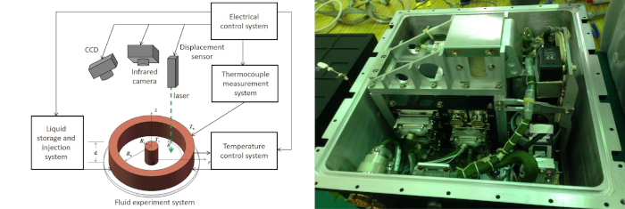
Figure 1: Space experimental payload. (Left) Schematic of the payload. (Right) Image of the space experiment payload. The thermocapillary convection can be observed by means of the infrared camera, CCD, and displacement sensor. Please click here to view a larger version of this figure.

Figure 2: Schematic and image of the annular liquid pool. When there was a temperature difference between the two ends, thermocapillary convection was generated inside the annular liquid pool. Please click here to view a larger version of this figure.

Figure 3: Vacuum filling device and the filling process. This procedure carried out before launch ensured that no bubbles were generated in the liquid during the space experiments. Please click here to view a larger version of this figure.
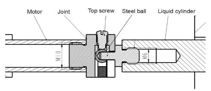
Figure 4: Schematic of the connection between the stepper motor and cylinder. The silicone oil discharge from or suction to the cylinder can be realized by controlling the push/pull switch of the stepper motor. Please click here to view a larger version of this figure.
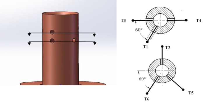
Figure 5: The installation locations of thermocouples. Temperature signals at different heights and azimuthal angles can analyze the traveling wave characteristics. Please click here to view a larger version of this figure.
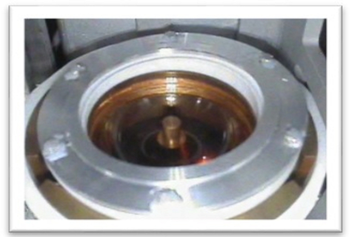
Figure 6: CCD image of the annular liquid pool (Case 13, Vr = 0.715). Whether the liquid level climbs or not can be identified by the image. The volume ratio can also be obtained by edge processing of the image. Please click here to view a larger version of this figure.
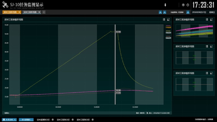
Figure 7: Real-time temperature control curve (Case 13, Vr = 0.715). This is a linear heating mode with a rate of 0.5 °C/min. Please click here to view a larger version of this figure.
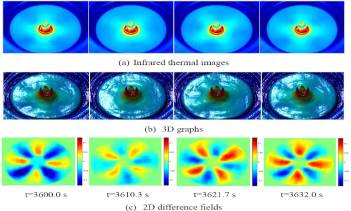
Figure 8: Temperature field on the free surface in one period (Case 13, Vr = 0.715). (A) Infrared thermal images of the hydrothermo wave. (B) Corresponding 3D graphs of (A). (C) Corresponding periodic subaverage images of original images in (A). The cold zone and the hot zone appear alternately in pairs. Red = high temperature; blue = low temperature. Please click here to view a larger version of this figure.

Figure 9: Temperature measurements (Case 13, Vr = 0.715). (Left) Temperature oscillation with the increase of the temperature difference. (Right) Corresponding critical frequency spectrum of signals in (A). PSD = Power spectral density. Please click here to view a larger version of this figure.

Figure 10: Oscillation measurements of the liquid-free surface (Case 13, Vr = 0.715). (Left) Displacement with the increase of the temperature difference. (Right) Corresponding frequency spectrum of signals in the left panel. When the temperature difference exceeds a certain threshold, the displacement will fluctuate periodically, and the amplitude increases as the temperature difference increases. Please click here to view a larger version of this figure.
Discussion
Due to the limitation of space resources, the volume of the equipment as a whole is only 400 mm × 352 mm × 322 mm, with a weight of only 22.9 ± 0.2 kg. This is very inconvenient when selecting and laying out experimental devices, and the establishment of the flow system becomes the critical step. Therefore, the increasing temperature difference is set at two ends of the liquid pool so that the fluid can generate a series of flow phenomena. In order to observe the entire process of the convection from steady to oscillation in a single experiment, 2cSt silicone oil is chosen as the working liquid because of its transparency and appropriate physical parameters. In addition, because of the surface tension, the liquid surface is curved. The observation point of the displacement sensor should be at the center of the inner and outer diameters.
Upon neglecting errors caused by physical properties, the uncertainty of the experimental parameters can be obtained. The synthetic standard uncertainty of the critical threshold of the thermocapillary convection was determined to be 1.11%. The uncertainty of the volume ratio caused by factors including liquid evaporation and volume reading is within 4.00%, among which the standard random uncertainties caused by temperature measurements and geometric dimensions of the liquid pool are 0.05 °C and 0.01 mm, respectively. The distance realized by the step motor for liquid injection/suction, and the minimum movement unit of the motor is 1 count = 3.5 × 10⁻⁶ mm. Combined with the uncertainties introduced by the liquid injection/suction and geometric dimensions of the liquid pool, the final synthetic uncertainty of the volume ratio is 4.07%.
Only 23 groups of valuable space experimental data have been obtained due to the limited flight time of the satellite, and experiments at a large temperature difference (above 40 °C) have yet to be carried out. In addition, due to the limitation of space resources, the model lacks rotation function compared with the real industrial crystal growth method.
In terms of equipment development, two key problems have been solved, namely the maintenance of the liquid-free surface and the liquid injection without bubbles, both of which play key roles in the successful implementation of space experiments. These two key technologies have also been successfully applied to subsequent space experiments, such as in the Tiangong-2 space mission, and will also be applied to additional space experiments in the future.
The experimental device and observation method based on SJ10 thermocapillary convection can provide a scientific basis and technical support for the study of fluid mechanics, microgravity physics, real industrial crystal growth, and possibly many other numerous applications.
開示
The authors have nothing to disclose.
Acknowledgements
There are many participants who have contributed to the work reported in this paper, including all the members of our project team, as well as some people from the Astronauts research and training center (ACC) and Neusoft.
This work is funded by the Strategic Priority Research Program on Space Science, Chinese Academy of Sciences: SJ-10 Recoverable Scientific Experiment Satellite (Grant No. XDA04020405 and XDA04020202-05), and by the joint fund of National Natural Science Foundation of China (U1738116).
Materials
| anti-creeping liquid | 3M | EGC-1700 | |
| CCD | WATTEC | WAT-230VIVID | |
| Displacement sensor | Panasonic | HL-C1 | |
| Heating film | HongYu | 125 Q/W335.1A | |
| Hydraulic cylinder | FESTO | ADVU-40-25-P-A | |
| Infrared camera | FLIR | Tau2 | |
| LED | 693 Institute | 10257MW7C | |
| Montor | PI | M-227 | |
| Montor controller | PI | C-863 | |
| Pipe, 4mm | FESTO | PUN-4X0,75-GE | |
| polysulfone plate | 507 Institute | ||
| Refrigeration chip | Zhongke | 9502/065/021M | |
| Silicon oil, 2cSt | Shin-Etsu | KF-96 | |
| Solenoid | FESTO | MFH-2-M5 | |
| Temperature controller | Eurotherm | 3304 | |
| Thermocouple, K-type | North University of China | ZBDX-HTTK |
参考文献
- Scriven, L. E., Sternling, C. V. The Marangoni effect. Nature. 187, 186-188 (1960).
- Effects of heating mode on steady antisymmetric thermocapillary flows in microgravity. Heat Transfer in Microgravity Systems, Trans. American Society of Mechanical Engineers Available from: https://heattransfer.asmedigitalcollection.asme.org/ (1994)
- Benz, S., Schwabe, D. The three-dimensional stationary instability in dynamic thermocapillary shallow cavities. Experiments in Fluids. 31, 409-416 (2001).
- Schwabe, D. Buoyant-thermocapillary and pure thermocapillary convective instabilities in Czochralski systems. Journal of Crystal Growth. 237-239, 1849-1853 (2002).
- Kamotani, Y., Ostrach, S., Pline, A. Analysis of velocity data taken in surface tension drivenconvection experiment in microgravity. Physics of Fluids. 6, 3601-3609 (1994).
- Kamotani, Y., Ostrach, S., Pline, A. A thermocapillary convection experiment in microgravity. Journal of Heat Transfer. 117, 611-618 (1995).
- Kamotani, Y., Ostrach, S., Pline, A. Some temperature field results from the thermocapillary flow experiment aboard USML-2 spacelab. Advances in Space Research. 22, 1189-1195 (1998).
- Kamotani, Y., Ostrach, S., Masud, J. Microgravity experiments and analysis of oscillatory thermocapillary flows in cylindrical containers. Journal of Fluid Mechanics. 410, 211-233 (2000).
- Schwabe, D., Benz, S., Cramer, A. Experiment on the Multi-roll-structure of thermocapillary flow in side-heated thin liquid layers. Advances in Space Research. 24 (10), 1367-1373 (1999).
- Schwabe, D., Benz, S. Thermocapillary flow instabilities in an annulus under microgravity results of the experiment MAGIA. Advances in Space Research. 29, 629-638 (2002).
- Kawamura, H., et al. Report on Microgravity Experiments of Marangoni Convection Aboard International Space Station. Journal of Heat Transfer. 134 (3), 031005 (2012).
- Sato, F., et al. Hydrothermal Wave Instability in a High-Aspect-Ratio Liquid Bridge of Pr > 200. Microgravity Science and Technology. 25 (1), 43-58 (2013).
- Yano, T., et al. Instability and associated roll structure of Marangoni convection in high Prandtl number liquid bridge with large aspect ratio. Physics of Fluids. 27 (2), 024108 (2015).
- Yao, Y. L., Liu, Q. S., Zhang, P., Hu, L., Liu, F., Hu, W. R. Space Experiments on Thermocapillary Convection and Marangoni Convection in Two Immiscible Liquid Layers. Journal of the Japan Society of Microgravity Application. 15, 394-398 (1998).
- Zhang, P., et al. Space experimental device on Marangoni drop migrations of large Reynolds numbers. Science in China. 44 (6), 605-614 (2001).
- Xie, J. C., Lin, H., Zhang, P., Liu, F., Hu, W. R. Experimental investigation on thermocapillary drop migration at large Marangoni number in reduced gravity. Journal of Colloid and Interface Science. 285, 737-743 (2005).
- Kang, Q., Cui, H. L., Hu, L., Duan, L., Hu, W. R. Experimental Investigation on bubble coalescence under non-uniform temperature distribution in reduced gravity. Journal of Colloid and Interface Science. 310, 546-549 (2007).
- Duan, L., et al. The real-time March-Zehnder interferometer used in space experiment. Microgravity Science and Technology. 20, 91-98 (2008).
- Zhu, P., Zhou, B., Duan, L., Kang, Q. Characteristics of surface oscillation in thermocapillary convection. Experimental Thermal and Fluid Science. 35, 1444-1450 (2011).
- Zhu, P., Duan, L., Kang, Q. Transition to chaos in thermocapillary convection. International Journal of Heat and Mass Transfer. 57, 457-464 (2013).
- Kang, Q., Duan, L., Zhang, L., Yin, Y. L., Yang, J. S., Hu, W. R. Thermocapillary convection experiment facility of an open cylindrical annuli for SJ-10 satellite. Microgravity Science and Technology. 28, 123-132 (2016).
- Wang, J., Wu, D., Duan, L., Kang, Q. Ground Experiment on the Instability of Buoyant-thermocapillary Convection in Large Scale Liquid Bridge with Large Prandtl Number. International Journal of Heat and Mass Transfer. 108, 2107-2119 (2017).
- Kang, Q., Jiang, H., Duan, L., Zhang, C., Hu, W. R. The Critical Condition and Oscillation – Transition Characteristics of Thermocapillary Convection in the Space Experiment on SJ-10 Satellite. International Journal of Heat and Mass Transfer. 135, 479-490 (2019).
- Kang, Q., et al. The volume ratio effect on flow patterns and transition processes of thermocapillary convection. Journal of Fluid Mechanics. 868 (108), 560-583 (2019).

