Enhancement Method of Surface Acoustic Wave-Atomizer Efficiency for Olfactory Display
概要
We establish here a method for coating the surface of a surface acoustic wave (SAW) device with amorphous Teflon film to improve the atomization efficiency required for application to an olfactory display.
Abstract
Since olfaction is an important sense in human interfaces, we have developed an olfactory display using a surface acoustic wave (SAW) atomizer and micro-dispensers. In this olfactory display, the efficiency of atomization is important in order to avoid smell persistence problems often encountered in human olfactory interfaces. Thus, the SAW device is coated with amorphous Teflon film to change the substrate nature from hydrophilic to hydrophobic. It is also necessary to silanize the piezoelectric substrate surface prior to Teflon coating to enhance the adhesion of the film. A dip coating method was adopted to obtain uniform coating on the substrate. The high-speed solenoid valve was used as micro-dispenser to spout a liquid droplet to the SAW device surface since its accuracy and reproducibility were high. Then, the atomization became easier on the hydrophobic substrate. In this study, the amorphous Teflon coating for minimizing the remaining liquid on the substrate after atomization was studied. The goal of the protocol described here is to show the methods for coating a SAW device surface with amorphous Teflon film and generating the smell using the SAW atomizer and a micro-dispenser, followed by a sensory test.
Introduction
Although devices for stimulating visual and auditory senses are popular, we cannot present all sensations that we perceive; though, we can ordinarily present a sensation using only these two senses. An olfactory display is a gadget that can present a scent, and it is used in virtual reality so that a user can perceive scents1,2,3,4,5,6,7. Since olfaction contributes to emotions greatly, an olfactory stimulus is indispensable for enhancing reality. We have previously studied movies, animations, and games with scents8,9.
Several researchers have studied olfactory displays; for example, Yanagida has studied a scent projector that delivers a scent to a specified person even when no one around him or her perceives it1. Yamada et al. have studied an odor source localization in virtual space using a simple Gaussian distribution model of odor concentration2. Kim et al. have proposed the concept of two-dimensional arrays of odor-releasing devices 3. Moreover, simple wearable olfactory displays and the ultrasonic phased array for controlling the direction of these scents have been proposed4,5,6.
One of the problems in olfactory display is smell persistence. A user may detect the smell even after it is intended to be changed to the air or another scent. Since it is preferable to switch between scents as quickly as possible in virtual reality, the smell persistence problem should be studied.
We have studied the olfactory display with a function of blending many ingredients. We previously developed this system using solenoid valves with high-speed switching10. Although it stably blends many ingredients, we could not yet solve the problem of smell persistence. Thus, we have since developed the olfactory display using micro-dispensers and a SAW atomizer11. Although similar techniques have been used to manipulate liquid droplets12,13,14, we applied it to scent generation. The SAW device is suitable for atomizing liquid droplets since it can atomize liquid droplets instantaneously15,16; however, we have found that tiny liquid droplets stay on a piezoelectric substrate after the atomization. These tiny liquid droplets cause smell persistence, even if most of the liquid is atomized.
Typically, a perfume is dissolved into a solvent such as ethanol to reduce viscosity. However, diluted perfume spreads onto the surface of a piezoelectric substrate due to its hydrophilic nature, and the atomization efficiency deteriorates when thin film spreads. Thus, a part of the liquid remains even after atomization, which cannot be removed even if RF power increases. Since the solvent evaporates soon after, only the perfume remains on and sticks to the substrate.
In this study, we coat the surface of a piezoelectric substrate with thin amorphous Teflon film so it becomes hydrophobic in nature. Since we can keep the droplet-like sphere on the hydrophobic surface, the energy required for detaching liquid from the substrate surface decreases. It is expected that an atomization efficiency is improved when the surface of SAW device becomes hydrophobic. The overall goal of this method is to improve the atomization efficiency so that a scent is immediately presented and can quickly disappear after its presentation, ultimately for application to olfactory display. In this paper, we show how a SAW device is coated with amorphous Teflon film and demonstrate the improvement of atomization efficiency and its experimental results were described in the reference17.
Protocol
The methods described here have been approved by the Human Research Ethics Committee of Tokyo Institute of Technology.
1. SAW Device Preparation and Checking Impedance
- Prepare a 10 MHz SAW device on a LiNbO3 substrate [128o-rotated Y-cut, X propagation, with 21 finger pairs of an IDT (inter-digitated transducer)], together with reflectors made of 32 finger pairs on one IDT side, as shown in Figure 1a.
Note: Figure 1b shows the principle of atomization. The SAW is converted to a longitudinal wave at the liquid droplet. Mist is generated due to acoustic streaming if the SAW energy is sufficiently large.
Note: The SAW device was fabricated by the manufacturer using typical photo lithography according to the electrode pattern that the authors designed. The piezoelectric substrate mentioned above was selected due to a high electromechanical coupling coefficient. - Mount the SAW device using aluminum foil and conductive paste on a printed circuit board made of aluminum (designed for this SAW device) where the SMA connector is attached (Figure 2).
Note: A printed circuit board made of aluminum is effective for heat radiation. - Measure the frequency characteristic of impedance using a network analyzer. The SAW device is connected to the analyzer via a coaxial cable connection from the printed circuit board. Frequency characteristics should show frequencies where imaginary parts of the device admittance go to zero, which are the SAW device resonance frequencies.
Note: When acoustic loss in the device is large, atomization does not occur. The acoustic loss can be checked by measuring the frequency characteristic of impedance. When the SAW device is coated with Teflon film, the difference between the frequency characteristics before and after coating should be monitored to check if the film is too thick.
2. Silanization
- Prepare the amino-based silane coupling agent (3-ahhminopropyltriethoxy silane). Adjust its concentration to 0.5 % (v/v) in water using a pipette.
Note: Silanization is mandatory to enhance the adhesion of amorphous Teflon coating. Teflon coating is removed during atomization if silanization is not performed. - Clean the surface of the SAW device using a cotton swab soaked with acetone.
- Set the device at a dip coater (Figure 3).
Note: A printed circuit board where the SAW device is fixed using mending tape is attached to the dip coater, since the thickness of the SAW device (0.5 mm) is too thin to be attached to the dip coater directly. - Pull down the device so that the atomization area can be immersed in the solution at a speed of 0.2 mm/s. Keep the device in solution for 5 min.
- Pull up the device at a speed of 1.7 mm/s. Keep the device in the air for 5 min.
- Rinse the device in pure water for 1 min.
- Keep the device in the air for 30 min.
3. Amorphous Teflon Coating
- Prepare the amorphous Teflon material and solvent for dilution. Adjust the concentration of the amorphous Teflon solution to 3% (v/v) using the solvent.
- Set the device at a dip coater (Figure 3).
Note: Dip coating was adopted here since the uniform coating is indispensable. Rough coating as well as coating that is too thick can cause deterioration of the atomization efficiency due to SAW attenuation. - Pull down the device so that atomization area is immersed in the solution at a speed of 0.2 mm/s. Keep the device in solution for 15 s.
- Pull up the device at the speed of 1.7 mm/s. Keep the device in the air for 5 min.
- Pull down the device so that atomization area is immersed in the solution at a speed of 0.2 mm/s. Keep the device in solution for 15 s.
- Pull up the device at the speed of 1.7 mm/s. Keep the device in the air for 30 min.
- Bake the device at 180 °C for 60 min using a hot plate.
Note: Thickness of the coating was approximately 400 nm according to quartz crystal microbalance (QCM) measurement.
4. Experimental Set-up for Atomization
- Mount the SAW device on a printed circuit board.
Note: Since the thickness of the SAW device is 0.5 mm, it can be easily broken. Thus, it is necessary to support it mechanically. - Measure the frequency characteristic of the SAW device impedance using a network analyzer. The SAW device is connected to the analyzer via a coaxial cable connection of the printed circuit board. Frequency characteristics should show frequencies where imaginary parts of the device admittance go to zero, which are the SAW device resonance frequencies
Note: Check the RF attenuation at the SAW device. The loss of the SAW device increases when it is inappropriately coated. This increase in loss typically occurs due to coating inhomogeneity or excessive thickness of coating; thus, the impedance characteristics before and after coating should be compared. The atomization cannot be performed if the SAW attenuation is too much. - Connect the SAW device to a function generator through an RF power amplifier.
- Set the waveform of the RF burst signal at a function generator (Figure 4a). The burst signal for the SAW device should be a sine wave, and its duty cycle should be 10%. The wave frequency should also be set to the SAW device resonance frequency obtained from the impedance characteristic measurements.
- Connect a burst square wave generator to a solenoid valve [i.e., micro-dispenser through a driving circuit (Figure 5)] so that a 24 V pulse signal can be supplied to the dispenser, which is also mentioned in the discussion18,19.
Tip: For driving solenoid valves, a transistor array is convenient. Up to eight solenoid valves can be driven using the transistor array in this study. - Set the micro-pump to apply pressure to flow the liquid to the micro-dispenser (Figure 5). The micro-pump supports the self-priming capability of the micro-dispenser20.
- Use an infrared thermometer to measure the temperature of the SAW device, if necessary.
Note: The temperature at the SAW device surface typically reaches around 45 °C when the RF burst signal (85 Vp-p and 10% duty cycle) is applied for 5 min.
5. Atomization
- Put the liquid (i.e., fragrance or chemical diluted with ethanol) into a vial.
- Set the waveform of the pulse signal applied to a micro-dispenser (Figure 4b). The pulse signal is a square wave pulse sequence with a 10% duty cycle and is generated with a function generator.
- Apply the pulse signal to the micro-dispenser to jet a liquid droplet to the SAW device18. Since a single droplet from the micro-dispenser is only a few nanoliters, a pulse sequence is needed to form a larger droplet for atomization.
- Apply the RF burst signal to the SAW device to atomize liquid droplets17. The burst signal is applied from a function generator through an amplifier after formation of the liquid droplets. The signal should be applied for as long as vapor is still generated from the atomization process.
Note: The RF burst signal is used to adjust the average RF power. The SAW device may have a crack if the RF power is much larger than 2 W. - Observe the surface of SAW device to inspect the remaining liquid droplet.
- Perform the same procedure as done in steps 4.1-4.7 and 5.1-5.5 for a bare SAW device. Then, compare the amount of remaining liquid droplet on the coated substrate with that from bare one.
6. Detecting Scents
- Put the liquid into a vial as done in step 5.1.
- Adjust the height of the SAW atomizer using a jack so that its height remains equal to the participant’s nose.
- Dispense the liquid onto the SAW device.
- Turn on the fan.
- Allow the participant to detect the scent.
Note: The authors did the sensory test instead of VOC analyzer used in the previous work since the perceived intensity rather than vapor concentration should be evaluated.
Representative Results
One microliter of ethanol was placed on both bare and coated LiNbO3 substrates (ethanol was typically used as a solvent for perfume). A thin film of ethanol solution was formed after it spread onto the substrate (Figure 6a); on the other hand, the sphere-like shape was kept on the coated substrate (Figure 6b). The contact angle of the one microliter of water increased from 50 to 110 degrees after amorphous Teflon coating (Figure 6c and 6d). It was found that the amorphous Teflon coating enhanced the hydrophobic nature. The sphere-like shape of the droplet was kept on the coated substrate, whereas the liquid spread into a thin film on the bare substrate.
Next, the experiment with atomization of 200 nL of lavender was performed (Figure 7). The subsequent images of atomization without and with coating are shown in Figure 7a and 7b, respectively. Timescale in the photos was obtained from the number of frames recorded by a digital camera. Lavender was diluted with ethanol (dilution ratio: 50:1 v/v). On the bare substrate, the liquid spread immediately after it was dispensed. At 33 ms, strong atomization occurred at the center of liquid, whereas only limited mist was generated at the liquid edge within the circle as shown in Figure 7a. At 100 ms, atomization stopped; so, although atomization occurred at first, it stopped soon after. Then, part of the liquid remained. While the solvent evaporated rapidly, partial solute remained on the substrate surface; thus, the remaining solute caused the serious smell persistence. On the other hand, the sphere-like shape with its contact angle of more than 90 degrees was maintained on the coated substrate after it was dispensed (Figure 7b). A concentrated mist was generated during atomization. After atomization, much less liquid in a smaller area was left in the smaller area compared to the bare substrate. Since the remaining liquid was not a smooth and complete surface but instead formed small single droplets, it is difficult to accurately calculate the coverage of droplets on Teflon coating. Roughly speaking, the remaining liquid on the hydrophobic surface was at most 10% of that on the hydrophilic surface.
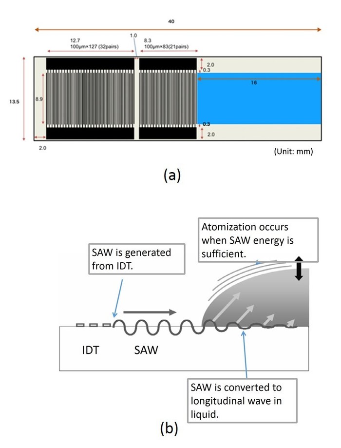
Figure 1: SAW atomizer. (a) Configuration of the SAW device and (b) principle of the SAW atomizer. Its electrode consists of gold and chromium. Figure 1a is reprinted with permission20. Please click here to view a larger version of this figure.
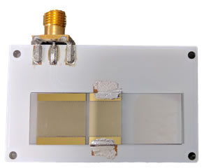
Figure 2: SAW device on a printed circuit board.
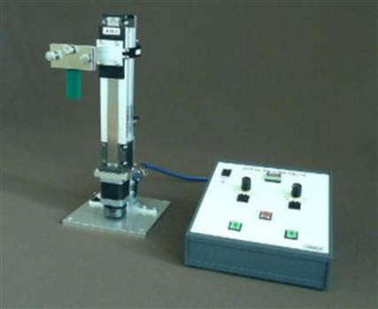
Figure 3: Dip coater used in this study.
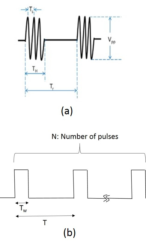
Figure 4: Time sequences. (a) Waveform of the RF burst signal. The typical values of Vpp and Tr are 85 Vp-p and 1 s, respectively. A typical duty cycle such as TH/Tr is 10%. (b) Waveform applied to a micro-dispenser. The typical Tw, T, and N are 1 ms, 10 ms, and 70 pulses, respectively.
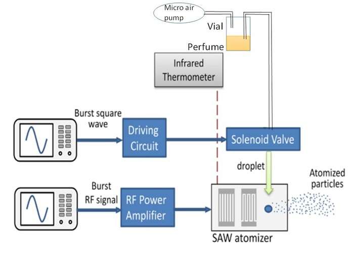
Figure 5: Experimental setup for atomizing liquid droplet. Please click here to view a larger version of this figure.
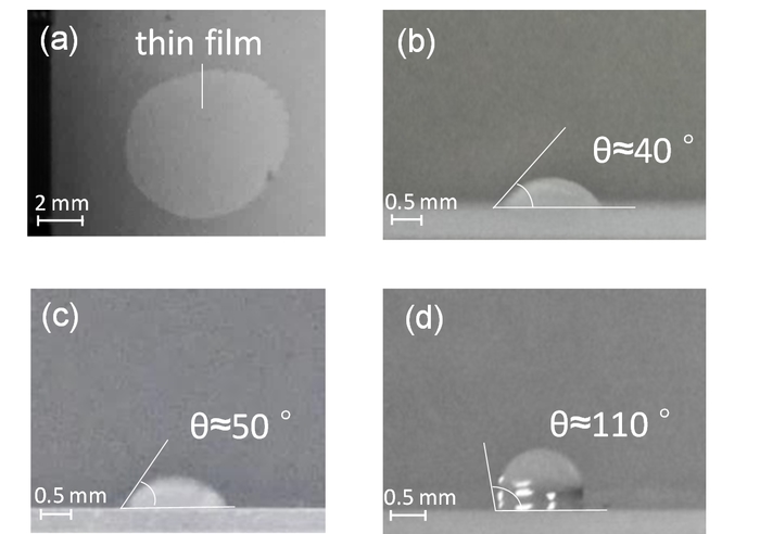
Figure 6: Comparison of liquid droplet shape between bare and coated subtrates. Shown are a (a) top view of the thin film on the bare lithium niobate surface and (b) side view of the liquid droplet on the coated one. One microliter of ethanol was used in both (a) and (b). Here, (c) and (d) show side views of one microliter of water on the bare and coated substrates, respectively. This figure was reproduced with permission17. Please click here to view a larger version of this figure.
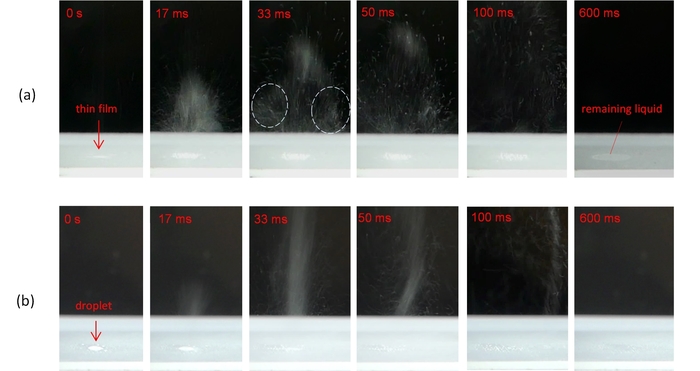
Figure 7: Atomization of the liquid droplet. Shown are the (a) hydrophilic surface (bare lithium niobate) and (b) hydrophobic surface (substrate coated with amorphous Teflon). The sample is 200 nL of lavender. This figure was reproduced with permission17. Please click here to view a larger version of this figure.
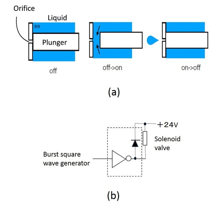
Figure 8: Micro-dispenser based upon a solenoid valve. Shown are (a) the micro-dispenser's principle and (b) a driver circuit for a single channel. This figure is reprinted with permission20. Please click here to view a larger version of this figure.
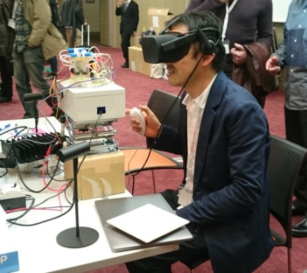
Figure 9: Application of the SAW atomizer coated with amorphous Teflon film. Research demonstration from the Intelligent User Interfaces (IUI) Symposium 2018 in Tokyo, Japan.
Discussion
One of the key components in this study is the micro-dispenser made of a high-speed solenoid valve18,19. Figure 8a shows the principle of this micro-dispenser. The plunger was driven by an electromagnetic coil. Its outlet is completely closed by the plunger during the OFF phase. The plunger rapidly moves to draw liquid in front during a short ON phase, then it moves back to the original location and jets a tiny liquid droplet from an orifice of the solenoid valve, which is driven by the circuit shown in Figure 8b. The amount of one liquid droplet is a few nanoliters. The frequency of the valve is between 1 and 1000 Hz, its minimum pulse width is 0.5 ms, and it works much faster than a typical solenoid valve. The typical distance between the orifice of the solenoid valve and the substrate was 15 mm. This study showed that the amount of liquid is precise and reproducible; moreover, it is robust against bubbles.
Smell persistence can be drastically reduced owing to amorphous Teflon coatingwhen an olfactory display based upon a SAW atomizer is used21. It can be further improved when a channel dedicated to deliver solvents to the substrate surface for cleaning is used.
The critical step in protocol is manually adjusting the excitation frequency of the atomizer when it deviates from the optimal one. This should be automatically performed in the future. A modification from the initial protocol was to include the silanization process since Teflon coating itself without silanization was atomized.
There are two remaining issues which limit this technique, one being the standing wave problem. The standing wave is generated when reflection occurs at the edge of the substrate. Since antinode and node appears periodically, atomization becomes weak at the node. Although we use a silicone gel to suppress the standing wave, this is not sufficient. A better material to absorb the acoustic energy is necessary.
The second limitation is the durability of the Teflon coating. The Teflon coating is partially removed after atomizing a liquid many times. Since the current condition for coating has not been studied extensively, the authors can optimize it to extend the durability of Teflon coating.
Nevertheless, the significance of the protocol with respect to existing methods is the reduction of remaining liquid after atomization on a surface with coating compared to without coating. Thus, the smell persistence is drastically reduced as is described elsewhere17. Using this SAW device, demonstration of the olfactory display was performed. The eight-component olfactory display to demonstrate cassis, orange, whiskey, and their mixture were presented to a user with Head Mount Display (Figure 9)19. In this situation, a SAW device with the proposed coating works well to suppress smell persistence, which otherwise can considerably deteriorate the quality of scent presentation.
The technique described here is important for olfactory display. Moreover, the SAW atomizer is applicable to a nebulizer for medical use and electrospray ionization for mass spectrometry. The atomization efficiency is also required in those applications.
開示
The authors have nothing to disclose.
Acknowledgements
This study was partially supported by JST Mirai program, Grant Number JPMJMI17DD.
Materials
| SAW device | Lightom | Custom-made | |
| Network analyzer | SDR-kits | DG84AQ VNWA 3E | |
| Dip coater | Aiden | DC4300 | |
| Silane coupling agent | Shin-etsu Chemical | KBE 903 | |
| Cytop amorphous teflon coating | Asahi glass | CT107MK | |
| Solvent for diluting cytop coating | Asahi glass | CT-SOLV100K | |
| Solenoid valve | Lee | INKA2438510H | |
| Transistor array | Texas Instrument | ULN2803A | |
| RF power amplifier | Mini-Circuits | ZHL-5W-1 | |
| Digital camera | Panasonic Corp | DMC-FZ300 | |
| Head Mount Display | Occulus | Occulus Rift Headset | |
| Hot plate | As One | HHP-170A |
参考文献
- Yanagida, Y. A survey of olfactory displays: Making and delivering scents. IEEE Sensors. , 1-4 (2012).
- Yamada, T., Yokoyama, S., Tanikawa, T., Hirota, K., Hirose, M. Wearable Olfactory Display: Using Odor in Outdoor Environment. IEEE Virtual Reality. , 199-206 (2006).
- Kim, H., et al. An X-Y addressablematrix odor-releasing system using an on-off switchable device. Angewandte Chemie. 123 (30), 6903-6907 (2011).
- Amores, J., Maes, P. Essence: olfactory interfaces for unconscious influence of mood and cognitive performance. CHI Conference on Human Factors in Computing Systems. , 28-34 (2017).
- Dobbelstein, D., Herrdum, S., Rukzio, E. inScent: A Wearable Olfactory Display as an Amplification for Mobile Notifications. International Symposium on Wearable Computers. , 28-34 (2017).
- Hasegawa, K., Qiu, L., Shinoda, H. Midair Ultrasound Fragrance Rendering. IEEE Transaction ON VISUALIZATION AND COMPUTER GRAPHICS. 24 (4), 1477-1485 (2018).
- Nakamoto, T. . Essentials of machine olfaction and taste. , 247-314 (2016).
- Nakamoto, T., Yoshikawa, K. Movie with scents generated by olfactory display using solenoid valves. Institute of Electronics, Information and Communication Engineers. E89-A (11), 3327-3332 (2006).
- Nakamoto, T., Otaguro, S., Kinoshita, M., Nagahama, M., Ohnishi, K., Ishida, T. Cooking up an interactive olfactory game display. IEEE Computer Graphics and Application. 28 (1), 75-78 (2008).
- Nakamoto, T., Minh, P. H. D. Improvement of olfactory display using solenoid valves. Proceedings of IEEE Virtual Reality Annual International Symposium. , 171-178 (2007).
- Hashimoto, K., Nakamoto, T. Tiny Olfactory Display Using Surface Acoustic Wave Device and Micropumps for Wearable Applications. IEEE Sensors Journal. 16 (12), 4974-4980 (2016).
- Beyssen, D., Brizoual, L. L., Elmazria, O., Alnot, P. Microfluidic device based on surface acoustic wave. Sensors and Actuators B: Chemical. 118 (1-2), 380-385 (2006).
- Wixforth, A., Strobl, C., Gauer, C., Toegl, A., Scriba, J., Guttenberg, Z. V. Acoustic manipulation of small droplets. Analytical and Bioanalytical Chemistry. 379 (7-8), 982-991 (2004).
- Heron, S. R., Wilson, R., Shaffer, S. A., Goodlett, D. R., Cooper, J. M. Surface Acoustic Wave Nebulization of Peptides as a Microfluidic Interface for Mass Spectrometry. Analytical Chemistry. 82 (10), 3985-3989 (2010).
- Kurosawa, M., Watanabe, T., Higuchi, T. Surface acoustic wave atomizer with pumping effect. IEEE Micro Electro Mechanical Systems (MEMS). , 25-30 (1999).
- Shiokawa, S., Matsui, Y., Ueda, T. Liquid streaming and droplet formation caused by leaky Rayleigh waves. Ultrasonics Symposium:Proceedings of the IEEE. 1, 643-646 (1989).
- Li, H., Qi, G., Kato, S., Nakamoto, T. Investigation and Improvement of Atomization Efficiency based on SAW Device Coated with Amorphous Fluoropolymer Film for Olfactory Display. Sensors and Actuators B: Chemical. 263 (15), 266-273 (2018).
- Kato, S., Nakamoto, T. Control system of micro droplet using micro-dispenser based on solenoid valve and its application for highly efficient SAW atomizer. IEEJ Transactions on Sensors and Micromachines. 138 (6), 220-225 (2018).
- Itou, S., Iseki, M., Kato, S., Nakamoto, T. Olfactory and visual presentation using olfactory display using SAW atomizer and solenoid valves. Proceedings of the 2018 Conference on Intelligent User Interface. , (2018).
- Nakamoto, T., Ito, S., Kato, S., Qi, G. Multicomponent olfactory display using solenoid valves and SAW atomizer and its blending-capability evaluation. IEEE Sensors Journal. , (2018).
- Kato, S., Nakamoto, T. Olfactory Display Based on Sniffing Action. IEEE Conference on Virtual Reality. , (2018).

