Infrared Degenerate Four-wave Mixing with Upconversion Detection for Quantitative Gas Sensing
Summary
Here, we present a protocol to perform sensitive, spatially resolved gas spectroscopy in the mid-infrared region, using degenerate four-wave mixing combined with upconversion detection.
Abstract
We present a protocol for performing gas spectroscopy using infrared degenerated four-wave mixing (IR-DFWM), for the quantitative detection of gas species in the ppm-to-single-percent range. The main purpose of the method is the spatially resolved detection of low-concentration species, which have no transitions in the visible or near-IR spectral range that could be used for detection. IR-DFWM is a nonintrusive method, which is a great advantage in combustion research, as inserting a probe into a flame can change it drastically. The IR-DFWM is combined with upconversion detection. This detection scheme uses sum-frequency generation to move the IR-DFWM signal from the mid-IR to the near-IR region, to take advantage of the superior noise characteristics of silicon-based detectors. This process also rejects most of the thermal background radiation. The focus of the protocol presented here is on the proper alignment of the IR-DFWM optics and on how to align an intracavity upconversion detection system.
Introduction
IR-DFWM provides the capability of measuring concentrations of IR active species down to the ppm level1, with spatial resolution. IR-DFWM has several advantages that make it an attractive technique for combustion research. Flames can be changed drastically by the insertion of probes, but IR-DFWM is nonintrusive. It has a spatial resolution, so species' concentrations at different points in the flame structure can be measured. It provides a coherent signal, which can be isolated from the thermal emission of the flame. Additionally, DFWM is less sensitive to the collision environment than, for instance, laser-induced fluorescence (LIF), which can be difficult to determine in a flame. The technique also provides access to molecular species that are IR active but lack visible or near-visible transitions that can be used to measure them with other techniques.
While DFWM has a number of advantages, alternative techniques might be preferable if one or more of these advantages are not needed. If spatial resolution is not needed, absorption-based techniques will be both simpler and more accurate. If the molecular species in question have transitions in the visible or near-IR region, LIF might be preferable, as LIF can provide spatially resolved information from a plane rather than just a single point. Under the right conditions, nonlinear methods, such as DFWM and PS, can also be used for single-shot 2D measurements2. The signal of these nonlinear methods is proportional to the probe beam intensity cubed, and as the pump beam must be expanded to cover the area of the 2D measurement, this requires either very high pulse energies or a combination of high third-order susceptibility, high concentrations, and low background noise to work. Therefore, it mostly depends on the molecular species whether this is a possibility.
In a more direct competition with DFWM, there are the other four-wave-mixing-based spectroscopic techniques: coherent anti-Stokes Raman spectroscopy (CARS), laser-induced grating spectroscopy (LIGS), and polarization spectroscopy (PS). CARS is a well-established technique for measuring the temperature and major species in combustion environments. However, it lacks the sensitivity to detect minor species, as the detection limit is usually approximately 1%2. PS and DFWM have previously been shown to have similar sensitivity and detection limits3; however, the signal-to-noise ratio of DFWM has been shown to increase by factor 500 when combined with upconversion detection4, while PS has shown only a 64-fold increase5. LIGS has the advantage of inducing a grating, using mid-IR light, but measures the effect by the refraction of a probe laser of this grating, and the wavelength of this probe laser can be chosen freely6. The wavelength of the probe laser can, therefore, be in the visible region, where fast, low-noise silicon-based detectors are available. This is the same advantage that is achieved by using upconversion. LIGS does have the drawback that it is very sensitive to collision2, which means that the concentration of major gas species must be known for precise concentration or temperature measurements with LIGS. If that issue is overcome, LIGS does have a similar sensitivity to both DFWM and PS at atmospheric pressure3, but where the LIGS signal increases with increasing pressure, the signal from DFWM and PS increases at lower pressures, which means the preferred technique will depend on the pressure environment.
Upconversion detection is the technique of converting a signal from long wavelengths to shorter ones by using sum-frequency generation. The advantage of this is that the detectors in the visible or near-infrared range have lower noise and a higher sensitivity than their counterparts in the mid-IR region. This was first investigated five decades ago7, but saw very little attention and use since then, due to the low conversion efficiencies. However, with advances in the production techniques for periodically poled lithium niobate (PPLN) and other materials with high nonlinear coefficients, as well the increased availability of high-power laser diodes (LDs), the technique has attracted increased attention in the last decade, with applications covering areas such as mid-IR single-photon detection8,9,10,11, IR lidar12,13, and hyperspectral imaging14,15 and microscopy16. The main advantage of combining upconversion detection with IR-DFWM is that the phase-match condition has a narrow angular and spectral acceptance band, which discriminates heavily against the thermal background, allowing the detection of weaker signals.
Protocol
The setup of the upconversion detector is shown in Figure 1; mirrors, lenses, or other optics referenced in the protocol are identified here or in the diagram of the IR-DFWM setup shown in Figure 2. The protocol section mainly deals with aligning the optical setup used for this method, and the process can be paused at any point by turning off all running equipment. All mirrors are adjusted manually. The software used here to control the camera and LD was delivered together with the upconversion detector. The use of the software is described at the end of the protocol.
1. Upconversion
- Place the end mirror of the alignment cavity, UH, as indicated in Figure 1.
- Remove the PPLN crystal from the crystal mount.
- Place an IR-sensitive card (sensitive at 1,064 nm) at position A, see Figure 1.
- Turn the angle of the kinematic mount holding UH to the extreme position in both the horizontal and vertical direction. Then, turn on the LD at approximately 1/3 of the maximum output.
- Align the alignment cavity as follows.
- Change the angle of UH by +0.2° in the horizontal direction.
- Sweep the vertical angle of UH from one extreme to the other, while watching the IR card for a beam from the alignment cavity.
- Repeat steps 1.5.1 and 1.5.2 until the cavity starts lasing.
- When the alignment cavity is lasing, switch between adjusting the angle of UH for a higher power and reducing the LD drive current. The LD is dimensioned to drive the full cavity, which has much higher losses than the alignment cavity. Keep the power where the beam leaving UH is easily visible with the IR card but no more than that.
- Remove the IR card.
- Adjust the angle of U2, so the alignment beam is reflected in the center of U3 (Figure 1).
NOTE: The beam from the alignment cavity should hit U2 in the center. - Adjust the angle of U3 so the beam continues to U4, U5, and U6 and is reflected from U6 to U7.
- The beam must pass through the PPLN mount at the height of the middle of the channels of the PPLN crystal, and it must enter the crystal perpendicular to the surface. Use U2 to correct the height and angle, while adjusting U3 to keep the beam level and centered through the holes x and y.
- Remove the germanium window and place the IR card behind U7, so that an IR beam leaving the cavity will hit the card, and the fluorescence will be visible to the person aligning the cavity.
NOTE: The alignment beam will now be passing through the PPLN mount and hit U7. - Adjust the angle of U7, so that the reflection from U7 passes back along the path of the alignment beam. While adjusting the angle of U7, watch for a beam on the IR card. When a beam is seen, adjust the angle of U7 to maximize the output.
- Mount the PPLN in the mount. Make sure the mount is placed so that the beam goes through one of the channels in the crystal.
- Continue with the substep (step 1.13.1, 1.13.2, or 1.13.3) matching the current situation.
- If an IR beam is still visible exiting U7, adjust U7 to maximize the output, and continue with the next step.
- If the IR beam exiting U7 is no longer visible, increase the LD current to 1/3 of the maximum output, and check if the IR beam can be seen. If a beam is visible, go to step 1.13.1; otherwise, go to step 1.13.3.
- Reduce the LD current to the previous level and trace the guide beam to see if it passes through the PPLN in the center of one of the channels. If it does not, repeat from step 1.7, but with the PPLN in the mount.
- Turn off the LD, remove UH, and attach the LP750 filter at position B (see Figure 1).
- Place the power meter behind U7 but leave space for checking the beam with an IR card. Then, turn on the LD at full power.
- If no signal is seen on the power meter, make small angle changes to U7, while watching for a signal on the power meter. If a signal is found, continue to the next step; otherwise, return to step 1.1.
- Optimize the cavity alignment by adjusting the angles of U2 and U7 to maximize power, while using a high-power IR card to check that the cavity is running in the fundamental Gaussian mode.
NOTE: While it might be possible to get higher power in a higher order mode, it is essential for the conversion efficiency that the laser is running in the fundamental mode. - If the cavity is not running in the fundamental mode, it will be running in a higher order mode where multiple lobes are visible on the IR card. Turn U7 so that the lobes are brought closer together on the IR card, until they merge.
- Record the power output at U7. Use this and the transmission of U7 to calculate the intracavity field. Compare this value to the calibration curve in Figure 6.
- When the cavity has been optimized, remove the LP750 filter, and reattach the germanium window.
2. IR-DFWM Alignment
NOTE: See Figure 2 for a diagram of the DFWM setup.
- Align the HeNe laser beam (the guide beam) with M3 and M4 to hit L1 in the center, going horizontally from M4 to L1.
- Insert BOXCARS plate 1 at a 45° angle to the beam (vertical direction) and ensure the beam goes through, producing two output beams.
- Insert BOXCARS plate 2 at a 45° angle to the beams (horizontal direction) and ensure the beam goes through, producing four output beams. Adjust the angles of the plates so the beams are spaced like the corners in a square.
- Adjust the position of L1 until the beams are equally spaced around the center of the lens.
- Leave the signal beam, which will be generated along the path of the beam blocked by the beam block, unblocked for now, so it can be used to align the rest of the setup. Place the iris so it blocks the three pump beams but allows the fourth beam, the signal beam, to pass through.
- Align L2 so the signal beam is collimated. This must be done using the focal lengths at the wavelength of the pulsed laser and not by visual inspection, as the focal lengths will be different for the wavelength of the guide beam and the mid-IR.
- Place M5 and M6 so that the guide beam is centered on the input window of the upconversion detector and perpendicular to the input window.
- Place L3 one focal length optical distance from the center of the PPLN. Take into account the refraction of the germanium window, the cavity mirror, and the PPLN itself.
- Set up the upconversion module and turn it on (see section 1).
- Remove the germanium window of the upconversion detector. This will allow a 1064 beam to exit the upconversion module.
- Overlap the HeNe laser beam and the 1064 beam from the upconversion detector by using M6 to move the 1064 beam onto the signal beam so that they overlap at L2, and by using M5 to move the guide beam onto the 1064 beam at L3. Alternate between the two mirrors until the guide beam and the 1064 follow the same path.
- Reattach the germanium window.
- Place several ND filters in the beam path, in front of the upconversion detector. Take great care to never let an unattenuated beam from the pulsed laser into the upconversion detector, as the high energy will likely damage the detector.
- Turn on the pulsed laser and ensure it is running stable and at an appropriate energy per pulse.
- Overlap the pulsed laser and the guide beam as follows.
- Adjust the angle of M1 till the pulsed laser overlaps the guide beam at the beam combiner (M2).
- Adjust the angle of the M2 so that the pulsed laser is reflected in the propagation direction of the guide beam.
- Check that the beams are overlapping at the beam combiner and at distances of 1 m, 2 m, and 3 m.
- Find the focal point of the beams after L1. Place the gas flow or flame to be measured so that the measurement point is at the focal point of the beams.
- Connect the trigger signal from the pulsed laser to the upconversion detector to time gate the detection. If the time delay and gate time are not known, start with a long duration of the time gate and narrow it down when the signal is found.
- Search the setup, especially the BOXCARS plates, for errant reflections and ensure they are blocked.
- Optimize the alignment of the signal beam in the upconversion detector as follows.
- If a signal is visible on the detector, adjust M5 and M6 to maximize the signal.
- If no signal is visible on the detector, reduce the ND filtering by one order of magnitude. Repeat until a signal is seen.
- If the signal on the detector is saturated, increase the ND filtering by one order of magnitude. Repeat until the signal is no longer saturated.
- Go through steps 2.19.1-2.19.3 until the signal can no longer be increased by adjusting M5 and M6.
- Place the beam block so that it blocks the signal beam, as indicated in Figure 2. Then, remove the ND filters.
- Adjust the position of the beam block to reduce any scattering (background noise) seen on the detector. Take great care not to unblock the beam accidentally and expose the detector to direct light from the pulsed laser.
- Prepare the gas flow or flame to be measured. Then, scan the pulsed laser across the wavelength range of interest, while recording the signal from the detector. This will generate a spectrum matching the gas composition at the overlap of the beams.
3. Laser Diode Software
- Run the LabVIEW program AuroraOne control.vi.
- Click the Laser TEC enable button to the on position and click the RW/TW safety button off.
- Set the laser current by entering the desired value in microwatts in the TA set point field. Entering a new value while the laser is running will adjust the current.
- Click the TA enable button to the on position to turn the laser diode current on.
- Turn off the laser diode by clicking the TA enable and the Laser TEC enable to the off positions.
4. IDS Imaging Development Systems
- Run the LabVIEW program UpconversionControl.vi.
- Under the tab Settings, set the shutter speed to 8 µs by typing the value in the field labeled Exposure Time (secs).
- Under the tab Settings, set the shutter type to Global in the field labeled IDS Shutter.
- Under the tab DBG, set the trigger type to Lo_Hi in the IDS trigger field.
- Under the tab DBG2, set the trigger delay in the field labeled IDS Trigger Delay (µs). This will depend on the delay between the trigger pulse and the laser pulse from the laser.
- Under the tab Settings, set the off set x and off set y to 480 pixels and the Larghezza and Altezza to 96 pixels.
- Under the tab Settings, set the frame rate to 0 in the Framerate field; this sets the camera to take one frame per trigger signal.
- Turn on the camera by pressing the Start Acquisition button.
- When a signal is entering the upconversion detector, the signal will be visible as a bright spot in the middle of the image shown on the right in the LabVIEW program. Use the Rect function on the left bar next to the image to draw a 6 x 6 pixel rectangle around the signal.
- View the average intensity from the selected pixels as a function of time under the History tab. If necessary, the graph can be cleared by right-clicking it and selecting clear.
- Press the Stop Acquisition button to stop the acquisition of new images from the camera.
- Export the data by right-clicking the intensity plot, select copy data to clipboard, and paste the data into a .txt file.
- Turn off the camera and control program by pressing the Shut down button.
Representative Results
Figure 3 shows the signal from different concentrations of HCN in N2, averaged over three scans for each concentration. The mixture was prepared by mixing 300 ppm HCN in N2 with pure N2 using mass flow controllers and heating it to 843 K. The central peak is the P(20) line of the ν1 vibrational band of HCN. The inset in Figure 3 shows the peak value of the signal from this line for each concentration, with a second-degree polynomial fit. The concentration dependency of the signal can be described by S = ax2 + b, where S is the signal and a and b are fitting constants17. Absolute concentration measurements in a flame require a calibration measurement as shown here, at a known temperature, to determine the constant a. The temperature in the measurement volume in the flame must also be measured as the constant a scales with temperature; a full discussion of this has already been published17. The poling period used for this measurement was 21.5 µm, with a crystal temperature of 104.5 °C.
Figure 4 presents raw data from a premixed flame. It shows five consecutive scans over the range 3229.5-3232 cm-1, each scan taking approximately 65 s. These cover three groups of waterlines, used for temperature measurements. Ideally, when working with a stable system, each scan over the same range should be identical, as the concentration, pressure, and temperature should be unchanged. The intensity of the lines seen here changes drastically from scan to scan, which is because the laser pulse mode and energy is not stable from scan to scan. Results like these are unusable unless the laser pulse energy has been recorded and can be used to sort measurements with sufficient laser pulse energy from the rest. The poling period used for this measurement was 21.5 µm, with a crystal temperature of 123 °C.
In Figure 4, the background scattering is not seen because an ND2 filter was used to reduce the signal, to avoid saturating the detector. For weaker signals, it was found that the background scattering is on the order of 5 pJ per pulse, which corresponds to the signal generated from the P(20) line of the ν1 vibrational band of 100 ppm HCN at room temperature.
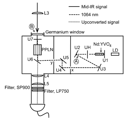
Figure 1: Diagram of the upconversion detector. U1-U7 and UH are mirrors, highly reflective (HR)-coated for 1,064 nm. All the mirrors are planes, except for U3, which has a 200 mm radius of curvature. Mirrors U1-U5 were made to be transmissive at the wavelength of the laser diode, to ensure that the LD light does not reach the detector. U6 is transmissive for the upconverted signal, 650-1,050 nm. U7 is transmissive for the mid-IR signal. UH is 95% reflective for 1,064 nm and 5% transmissive. The path length from U1 to U3 is 156 mm, and the path length from U3 to U7 is 202 mm. L4 and L5 are achromatic lenses with 60 mm and 75 mm focal lengths, respectively. Both are transparent for 650-1,050 nm. The camera used as detector is placed 75 mm from L5. The cavity field is vertically polarized. The PPLN used here has poling periods of 21.0 µm, 21.5 µm, 22.0 µm, 22.5 mm, and 23.0 µm, and the crystal length is 20 mm. The visible and near-infrared detector used is a UI-5240CP-NIR-GL camera from IDS Imaging Development Systems. Please click here to view a larger version of this figure.
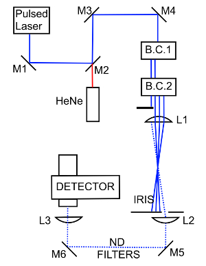
Figure 2: Diagram of the DFWM setup. M1 is a dielectric mirror highly reflective (HR) at the wavelength of the pulsed laser. M2 is a dielectric mirror coated to be HR at the wavelength of the pulsed laser and transmissive for the HeNe guide beam. M3-M6 are protected gold mirrors. B.C.1 and B.C.2 are BOXCARS plates 1 and 2. L1 is a 500 mm focal length CaF2 lens with a 5.1 cm diameter. L2 is a 500 mm focal length CaF2 lens with a diameter of 2.54 cm. L3 is a 100 mm focal length CaF2 lens. The pulsed laser is vertically polarized. Please click here to view a larger version of this figure.
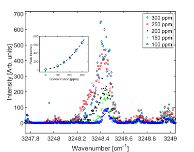
Figure 3: Signal from different concentrations of HCN in N2. The central peak is the P(20) line of the ν1 vibrational band of HCN. The inset shows the peak signal from each concentration (diamond markers), with a second-order polynomial fit. Please click here to view a larger version of this figure.
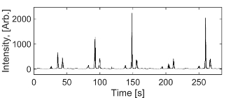
Figure 4: Five consecutive scans of ca. 65 s in duration per scan, done in a premixed flame. The laser was scanned over the range of 3229.5-3232 cm-1. The peaks seen here are the signal from several collections of H2O transition lines. The signal was reduced with an ND1 and an ND0.6 filter, to avoid saturating the detector. Please click here to view a larger version of this figure.
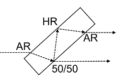
Figure 5: A BOXCARS plate seen from the side. It is a block of transparent material. On the input side, it is coated with an antireflective coating on half of the surface. The laser beam enters here and reaches the output side, where half the surface is coated for a 50% transmission. The light reflected internally in the plate is then refracted to the part of the input side coated for high reflection and is reflected through the top half of the output side. This splits one beam into two parallel beams. The same effect could be achieved with a beam splitter and a mirror, but a beam splitter would have some reflection from the rear surface, which could increase the background noise. Also, the BOXCARS plate requires no alignment to ensure the two beams produced are parallel. Please click here to view a larger version of this figure.
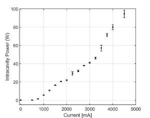
Figure 6: Intracavity power as a function of pump laser diode current for the upconversion module. Each point is an average of the power measured from three separate alignments of the cavity and the error bars indicate the spread between the separate alignments. The deviation from the ideal laser behavior is caused by thermal effects in the laser crystal and the PPLN crystal. Please click here to view a larger version of this figure.
Discussion
The precision of the alignment of the pulsed laser beam is critical to the sensitivity of the method. Special care must be taken to ensure that the beams are separated by equal distance after the BOXCARS plates and that the beams are equally spaced around the center of L1. Deviation from this will lead to a significant drop in signal intensity and, therefore, sensitivity. Likewise, care must be taken that the upconversion module cavity is running in the fundamental mode and that the signal beam is aligned for an optimal overlap with the upconversion pump. The signal can easily be reduced by one or two orders of magnitude if the upconversion cavity is running in a wrong mode or the signal beam overlap with the cavity field is suboptimal. This includes placing L3 with millimeter precision so that the signal beam focal point is in the middle of the PPLN crystal. With an optimal overlap and 80 W of cavity power, a 6% quantum efficiency of the SFG stage is possible. With the detector and wavelength used here, the total detection efficiency is 3%. The maximum intracavity power that can be reached is 120 W, but 80 W can be achieved reliably. The conversion efficiency is proportional to the intracavity power, so signals recorded with a different intracavity power can be compared if the intracavity power is recorded.
The main limiting factor for the sensitivity of this method is the background scattering, which drowns weak signals. To limit this scattering, it is critical that the optics are kept dust-free, especially lens L1. Care must also be taken that the position of the beam block minimizes the background noise. The beam block should be placed on an xy-stage so that it can be moved in a controlled manner in both the horizontal and vertical plane, perpendicular to the direction of the beams.
The scanning discussed here is done with the PPLN at a constant temperature. The conversion efficiency is proportional to sinc(ΔkL/2π)2, where Δk is the phase mismatch and L is the crystal length. The full width half maximum (FWHM) of this function is the bandwidth of the detector at a constant PPLN crystal temperature. The FWHM of this function changes with the crystal temperature and wavelength but is generally on the order of 5 cm-1 in the mid-IR, for a 20 mm long crystal. The exception is near 4,200 nm, where the width increases greatly18.
No scaling optics have been included in the setup diagram in Figure 2, because there are a number of issues to consider before deciding what, if any, scaling is needed. For the setup described here, the pulsed laser beam is collimated at a beam diameter of ca. 2 mm when reaching L1. This gives a beam waist at the focal point of approximately 400 µm, using a wavelength of 3 µm. When implementing this technique, it might be desirable to change the focal length of L1, either because more space is needed between L1 and the focal point for practical reasons, or to shorten the measurement volume by increasing the convergence angles, which can be done by using a shorter focal length. In this case, the beam waist at the focal point should be kept at ca. 400 µm and the collimated beam should be scaled to match. It should, however, be taken into account that increasing the beam diameter without increasing the spacing of the beams will increase the scattering from the beam block edges. The spatial resolution is given by the overlap of the pump beams. For the setup described here, the overlap is 6 mm long, so the measurement volume is a cylinder of 6 mm long, with a radius of 0.4 mm.
To achieve quasi-phase-matching in the PPLN crystal, both the mid-IR signal and the intracavity field of the upconversion cavity must be extraordinarily polarized in the PPLN crystal. The upconversion cavity should be built so that the polarization of the intracavity field is automatically right. If the mid-IR laser does not already match this, a waveplate can be inserted at the mid-IR laser output to turn the polarization.
IR-DFWM requires relatively high energy pulses, 1-4 mJ, combined with a narrow enough laser linewidth to resolve molecular lines, which are on the order of 0.1 cm-1. Lasers that match these criteria generally have low repetition rates, and as data acquisition with DFWM is generally done by scanning the wavelength of the laser, this limits measurements speed. This means the method is most readily applied to measurements where the subject does not change over time, although it has also been applied to temporally resolved measurements17. Another limitation is that, because of the sensitivity to scattered light, particles in or near the measurement volume will create scattering events that completely drown the signal17. The phase-match condition of the upconversion process is spectrally narrow, which helps eliminate noise from the thermal background radiation, but it does make scans over broad wavelength ranges more time-consuming as the PPLN temperature must be tuned to keep the signal wavelength phase-matched.
Future uses of IR-DFWM are planned for the detection of NH3 in flames, or to continue the work with HCN in more practical environments. The most obvious means for improving the method is to further reduce the background from scattered light. This might be done using spatial filtering of the signal beam after the signal is collected by L2.
Divulgazioni
The authors have nothing to disclose.
Acknowledgements
The funding received by the authors within the scope of Horizon 2020 by the European Union is highly appreciated. This work was conducted as part of the Mid-TECH Marie Curie innovative training network [H2020-MSCA-ITN-2014-642661].
Materials
| Nd:YAG laser, pulsed | Spectra Physics | Quantarau Pro-290-10 | Quantity: 1 (For pumping the mid-IR laser) |
| Nd:YAG laser, injection seeding system | Spectra Physics | 6350 | Quantity: 1 |
| NIR Dye laser – OPA system | Sirah | OPANIR | Quantity: 1 |
| HeNe laser | Thorlabs | HNL100LB | Quantity: 1 |
| Dichroic mirror | LASEROPTIK | NA | Quantity: 1, custom order: HR for the mid-IR, transparent for 632 nm |
| Protected Gold Mirrors | Thorlabs | PF10-03-M01 | Quantity: 5 |
| BoxCars Plate | LASEROPTIK | NA | Quantity: 2, Custom order |
| xy-stage | Thorlabs | DTS25/M | Quantity: 2 |
| 500 mm focal length CaF2 lens, Ø2'' | Eksmaoptics | 110-5523E | Quantity: 1 |
| 500 mm focal length CaF2 lens, Ø1'' | Thorlabs | LA5464 | Quantity: 1 |
| 100 mm focal length CaF2 lens, Ø1'' | Thorlabs | LA5817 | Quantity: 1 |
| Iris, Ø50 mm | Thorlabs | ID50/M | Quantity: 1 |
| ND1 IR filter (ZnSe) | Thorlabs | NDIR10B | Quantity: 1 |
| ND2 IR filter (ZnSe) | Thorlabs | NDIR20B | Quantity: 1 |
| ND3 IR filter (ZnSe) | Thorlabs | NDIR30B | Quantity: 2 |
| Upconversion Detector | NLIR | NA (closest equivalent: U3055 3.0-5.5µm) | Quantity: 1, Custom order |
| VIS/NIR Detector Card | Thorlabs | VRC2 | Quantity: 1, (low intensity) |
| NIR Detector Card | Thorlabs | VRC4 | Quantity: 1, (high intensity) |
| MIR Detector Card | Thorlabs | VRC6S | Quantity: 1 |
| Thermal Power Sensor Head | Thorlabs | S302C | Quantity: 1 |
| Power meter console | Thorlabs | PM100D | Quantity: 1 |
Riferimenti
- Sahlberg, A. -. L., Zhou, J., Alden, M., Li, Z. Investigation of ro-vibrational spectra of small hydrocarbons at elevated temperatures using infrared degenerate four-wave mixing. Journal of Raman Spectroscopy. 47 (9), 1130-1139 (2016).
- Kiefer, J., Ewart, P. Laser diagnostics and minor species detection in combustion using resonant four-wave mixing. Progress in Energy and Combustion Science. 37 (5), 525-564 (2011).
- Sahlberg, A. -. L. Non-linear mid-infrared laser techniques for combustion diagnostics. Lund University. , (2016).
- Høgstedt, L., et al. Low-noise mid-IR upconversion detector for improved IR-degenerate four-wave mixing gas sensing. Optics Letters. 39 (18), 5321 (2014).
- Pedersen, R. L., Hot, D., Li, Z. Comparison of an InSb Detector and Upconversion Detector for Infrared Polarization Spectroscopy. Applied Spectroscopy. 72 (5), 793-797 (2018).
- Sahlberg, A. -. L., Kiefer, J., Aldén, M., Li, Z. Mid-Infrared Pumped Laser-Induced Thermal Grating Spectroscopy for Detection of Acetylene in the Visible Spectral Range. Applied Spectroscopy. 70 (6), 1034-1043 (2016).
- Midwinter, J. E. Image conversion from 1.6 µ to the visible in lithium niobate. Applied Physics Letters. 12 (3), 68 (1968).
- Dam, J., Tidemand-Lichtenberg, P., Dam, J. S., Tidemand-Lichtenberg, P., Pedersen, C. Room-temperature mid-infrared single-photon spectral imaging. Nature Photonics. 6 (11), 788-793 (2012).
- Pelc, J. S., et al. Long-wavelength-pumped upconversion single-photon detector at 1550 nm: performance and noise analysis. Optics Express. 19 (22), 21445-21456 (2011).
- Mancinelli, M., et al. Mid-infrared coincidence measurements on twin photons at room temperature. Nature Communications. 8 (2), 1-8 (2017).
- Sua, Y. M., Fan, H., Shahverdi, A., Chen, J. -. Y., Huang, Y. -. P. Direct Generation and Detection of Quantum Correlated Photons with 3.2 um Wavelength Spacing. Scientific Reports. 7 (1), 1-10 (2017).
- Meng, L., et al. Upconversion detector for range-resolved DIAL measurement of atmospheric CH4. Optics Express. 26 (4), 3850-3860 (2018).
- Xia, H., et al. Long-range micro-pulse aerosol lidar at 1.5. µm with an upconversion single-photon detector. Optics Letters. 40 (7), 1579-1582 (2015).
- Junaid, S., et al. Mid-infrared upconversion based hyperspectral imaging. Optics Express. 26 (3), 2203-2211 (2018).
- Kehlet, L. M., Tidemand-Lichtenberg, P., Dam, J. S., Pedersen, C. Infrared upconversion hyperspectral imaging. Optics Letters. 40 (6), 938-941 (2015).
- Hermes, M., et al. Mid-IR hyperspectral imaging for label-free histopathology and cytology. Journal of Optics. 20 (2), 023002 (2018).
- Hot, D., et al. Spatially and temporally resolved IR-DFWM measurement of HCN released from gasification of biomass pellets. Proceedings of the Combustion Institute. , (2018).
- Barh, A., Pedersen, C., Tidemand-Lichtenberg, P. Ultra-broadband mid-wave-IR upconversion detection. Optics Letters. 42 (8), 1504 (2017).

