Setting Up a Simple Light Sheet Microscope for In Toto Imaging of C. elegans Development
Summary
This protocol describes the setup of a light sheet microscope and its implementation for in vivo imaging of C. elegans embryos.
Abstract
Fast and low phototoxic imaging techniques are pre-requisite to study the development of organisms in toto. Light sheet based microscopy reduces photo-bleaching and phototoxic effects compared to confocal microscopy, while providing 3D images with subcellular resolution. Here we present the setup of a light sheet based microscope, which is composed of an upright microscope and a small set of opto-mechanical elements for the generation of the light sheet. The protocol describes how to build, align the microscope and characterize the light sheet. In addition, it details how to implement the method for in toto imaging of C. elegans embryos using a simple observation chamber. The method allows the capture of 3D two-colors time-lapse movies over few hours of development. This should ease the tracking of cell shape, cell divisions and tagged proteins over long periods of time.
Introduction
The formation and shaping of an organism involves cell movements, cell shape changes, cell division and cell differentiation. Understanding the progression and coordination of these processes require fast imaging tools with three-dimensions capability and subcellular resolution. Amongst the techniques with these in vivo imaging capabilities, light sheet illumination microscopy also called single/selective plane illumination microscopy has the unique advantage of producing low-phototoxic effects and low-photobleaching1,2.
In sheet illumination microscopy, the sample is illuminated from the side by a light sheet, which performs the optical sectioning. The illumination path and the detection path are perpendicular to each other and the light sheet is aligned to coincide with the object focal plane of the detection objective lens. The sample is placed at the intersection of the two paths, and can be moved along the detection axis to allow 3D imaging. Only the plane of interest is illuminated and all the points of this plane are detected at the same time. This significantly increases the acquisition speed and reduces photobleaching as well as phototoxicity in comparison to confocal microscopy3.
Practically, sheet illumination microscopy is easy to setup and align: for two dimensional imaging, no scanning is necessary neither for the detection part, nor for the illumination part; as a wide-field technique with sectioning capability, three-dimensional imaging can be obtained by a single axis movement of the stage holding the sample.
Here we present the setting up of a simple light sheet microscope and its implementation for in toto imaging of C. elegans embryos. C. elegans embryos are well suited to live in vivo imaging due to their transparency, invariant lineage and stereotyped cell positions4,5. The developed light sheet setup is based on a standard upright microscope for the detection. The protocol presented below details how to build and align the excitation module/path, test and characterize the light sheet and mount the sample for 3D imaging. It also provides examples of time-lapse movies acquired with the setup on various strains expressing fluorescent markers.
Protocol
1. Setting up the Light Sheet and the Detection Path
Figure 1 gives a general scheme of the optical setup.
- Place and fix the microscope and the lasers on the optical table.
- Combine lasers 488 nm, 561 nm and 405 nm with the corresponding dichroic mirrors. After the dichroic mirrors, the lasers have to be precisely co-aligned. Note that the choice of the laser wavelengths, dichroic mirrors, and optical filters is determined from the absorption spectra of the specific fluorescent labels used in the experiments.
- Place the acoustic-optical tunable filter (AOTF). Use the test sheet provided by the supplier to adjust the frequency and power of the AOTF. When well-aligned, about 90% of the laser power is transmitted at a maximum tuning as measured by a powermeter. Note that some lasers can be fully controlled by software, which could make the AOTF unnecessary.
- Place and fix the telescope. Note that the telescope is composed of two lenses that expand the beam to a width equal or bigger than the diameter of the back aperture of the illumination objective lens. The lens with the smallest focal length should come first.
- Place, align and fix the periscope bringing upwards the optical path closer to the back aperture of the cylindrical lens. Note that the two mirrors of the periscope are mounted in a way that their long axis is laying on the inclination of the mirror in order to reflect the fully expanded beam.
- Place the cylindrical lens next to the periscope exit. Note that the cylindrical lens focuses the beam in one direction and leaves it collimated in the other direction, thereby forming a light sheet.
- Refocus the resulting light sheet by using the illumination objective lens. Note that the image focal point of the illumination objective should coincide with the object focal point of the detection objective. Project the beam on a screen (e.g. a wall) at a long distance. Move the illumination objective along the illumination beam axis to obtain on the screen sharp contours of the light sheet.
- Place the quad line (405/488/561/638) emission filter in the place reserved in the microscope (cube).
- Place the EMCCD camera at the microscope output port.
- Fix the first manual translation stage on the microscope stage by screws in holes drilled in the microscope stage. Note that the edge of the translation stage has to be positioned at about 2 cm away from the center of the microscope stage, so that the cuvette is centered below the detection objective lens.
- Fix the second manual translation stage on the first one. The directions of the two stages have to be perpendicular (X and Y translations).
- Fix the Z piezoelectric stage at the top of the two previous stages. Note that a motorized stage can be used instead of the piezoelectric stage.
- Fix the cuvette holder (see Figure 2) at the top of the stages. The cuvette will thus be placed at the intersection of the illumination path and the detection path, which are perpendicular to each other.
2. Checking the Light Sheet
- Fill a glass cuvette with fluorescent solution, and place it on the sample holder at the intersection of the two optical paths. The light sheet is thus visible. It has to be horizontal, and symmetric/centered with respect to the detection objective lens.
- Remove the cylindrical lens and acquire an image to measure the thickness of the light sheet. Note that the thickness of the light sheet depends on the numerical aperture (NA) of the illumination objective lens (about 3-4 µm for NA = 0.3). Note that for a given lens, the thickness of the light-sheet can be increased by reducing the size of the beam entering the back aperture with a slit. Note that fluorescent microspheres can be used to measure the axial and lateral resolution of the microscope.
- Put back the cylindrical lens before starting the experiment.
3. The mounting of C. elegans Embryos
The following steps are pictured in Figure 3.
- Use a diamond-marking pen to cut a piece of a glass slide of 10 x 20 x 1 mm.
- Prepare 5% bacto-agar in water, boil it and maintain it in a heater block at 60 °C.
- Add 50 µl of poly-L-lysine on one side of the cut piece of slide, allow it to dry.
- Place a microscope slide on the bench and fix it.
- Juxtapose the cut piece of slide with the fixed slide and add a drop of melted agar on the top. Squeeze the agar using another clean microscope slide to obtain a thin agar pad.
- Allow the agar pad to dry before removing the top slide.
- Cut the agar pad on the side of the fixed slide in order to leave an excess of approximately 3 mm of agar and remove gently the fixed slide.
- Add 50 µL of poly-L-lysine on the agar and let it dry completely.
- Put gravid worms in M9 medium in a watch glass.
- Cut the worms at the level of the vulva with a scalpel to release the embryos.
- Under a binocular identify the embryos at the stage of interest and collect them by using a microcapillary pipette.
- Place the embryos on the part of the agar coated with poly-L-lysine that protrudes from the cut piece of slide. Place the embryos just next to the border of the slide. Do not position the embryos at the border of the agar because they won’t be stable enough. Remove gently the liquid so that the embryos will stick on the poly-L-lysine layer.
- Quickly align the embryos to avoid desiccation.
- Place the cut slide in a plastic Petri dish and gently add M9 medium to cover the slide.
- Check under a binocular that the eggs are still stuck on the agar.
4. Recording of C. elegans Development
- Fix the previous preparation (cut slide, agar plus embryos) in the sample holder and place it in a cuvette. Figure 4 describes the homemade holder and Figure 5 shows a view of the cuvette in observation context.
- Fix the cuvette on the piezoelectric stage.
- Identify the position of the embryos with bright field illumination.
- Start the home-made software controlling the AOTF, the camera and the piezoelectric stage. Note that a free software, such as micromanager, can also be used.
- Select the laser line and power (AOTF).
- Adjust the position of the light sheet using the 3 directions stage supporting the cylindrical lens and the illumination lens. Move the stage along the lateral direction (X) to obtain the brightest signal. Adjust then the Z position of the light sheet, and the longitudinal position (Y) to obtain the best signal to noise ratio. Note that the position of the light sheet focus may need to be adjusted from one embryo to another to correct differences in light path lengths.
- To acquire time-lapse images, select the exposure time, gain, time between two images, as well as the number of images to be acquired, and the laser power. For 2 color acquisition, select a second laser line. Two color images are acquired consecutively.
- To acquire a z stack, also select the distance between the two slices, and the beginning and ending positions of the piezoelectric.
Representative Results
Three 3D time-lapse recording experiments from three different C. elegans strains illustrate the type of data that can be obtained using the light sheet microscope setup described above. We checked that under these conditions the embryos develop at normal speed and survive the imaging, consistent with earlier reports indicating that SPIM imaging causes only low phototoxicity levels in C. elegans embryos6,7.
The first strain expresses an histone fused to GFP (zuIs178;stIs10024). Recording was performed during 2 hours with a stack of 20 slices (distance between slices 1 μm) taken every 37 sec. Figure 6 illustrates one plane of the stack at different time points. Both interphasic nuclei (arrow) and condensed mitotic chromatin (arrow head) are clearly visible.
The second strain expresses a tubulin fused to GFP (ruIs57) and an histone fused to mCherry (itIs37; stIs10226). Recording was performed during 16 min with a stack of 20 slices (distance between slices 1 μm) taken every 105 sec. Figure 7 illustrates different planes of the stack and different time points. The associated movie 1 displays 3D reconstructions at 3 successive time points. During division, the mitotic spindle (green) and condensed chromosomes (red) are clearly visible allowing the tracking of the cell division orientations during development.
The third strain expresses the apolipoprotein VIT-2 fused to GFP (pwIs23) and a membrane bound mCherry (ltIs44). Recording was performed during 25 min with a stack of 10 slices (distance between slices 1 μm) taken every 30 sec. Figure 8 illustrates different planes of the stack and different time points. The fast movements of the yolk lipoprotein particles (green) within the cells can easily be followed.
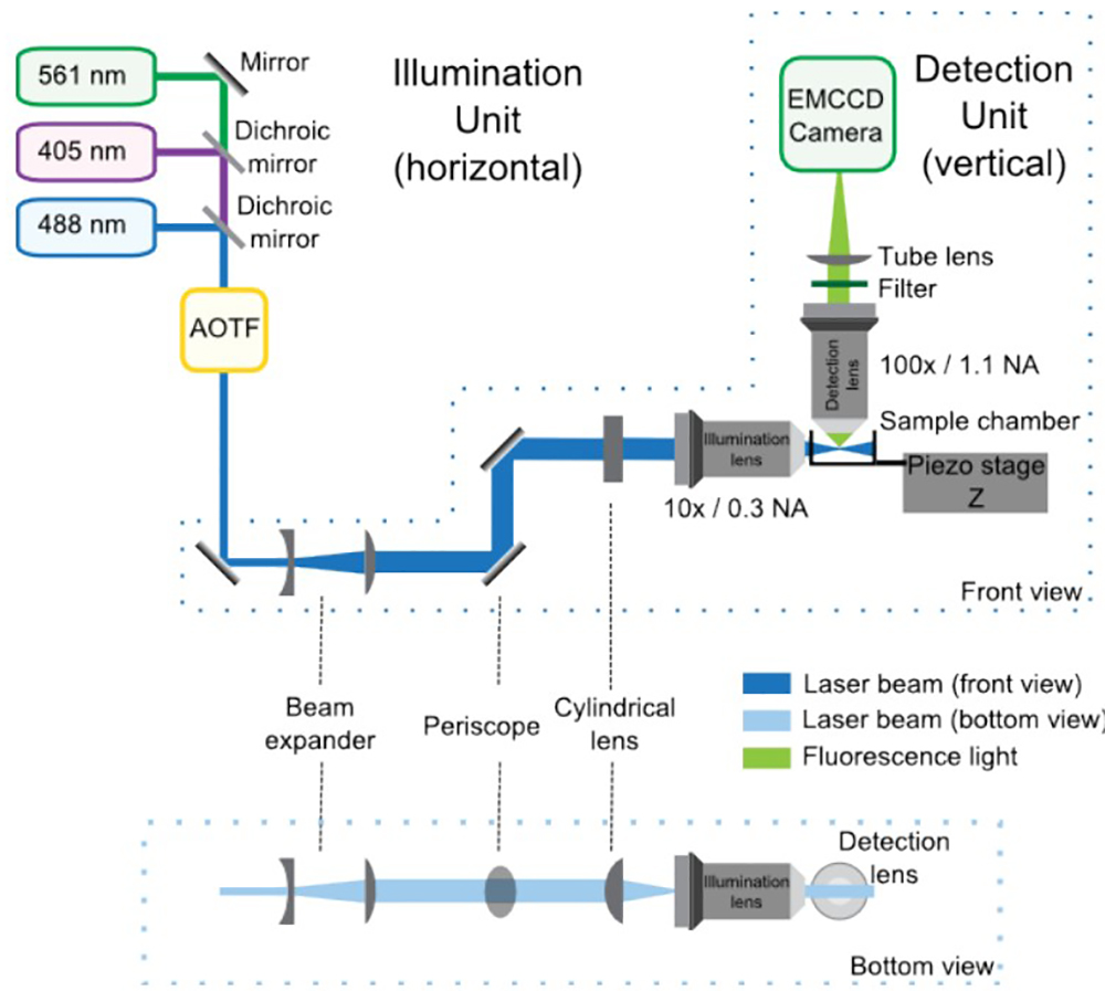
Figure 1: SPIM optical setup composed of the illumination and detection units, front and bottom views. In the illumination unit, the lasers combined by the dichroic mirrors enter the AOTF, which controls the power of each laser independently. Then, the telescope increases the size of the beam by 4-fold and the periscope brings it to the height of the microscope. The cylindrical lens forms the light sheet, which is refocused by the illumination objective. The detection unit is integrated in the upright microscope and is mainly composed by the detection lens, the filter, the tube lens and the EMCCD. The sample is positioned at the intersection between the illumination and detection paths. A piezoelectric stage allows vertical (Z) displacements of the sample for 3D acquisition.
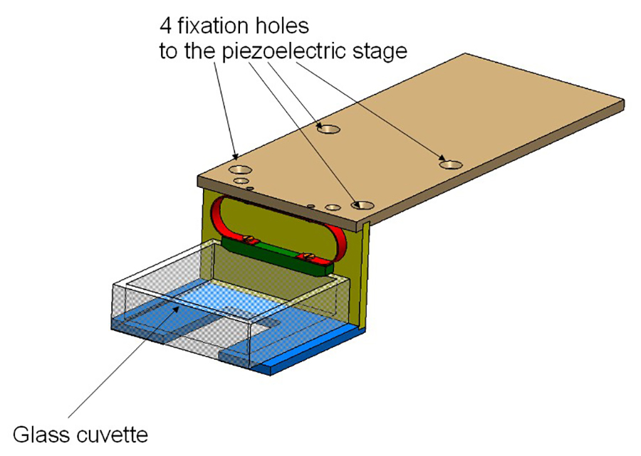
Figure 2: Cuvette holder. The holder consists of 3 aluminum plates and is screwed on the piezoelectric stage. The glass cuvette is held by a spring (in red).
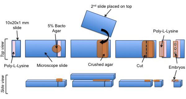
Figure 3: Mounting protocol of C. elegans embryos for SPIM experiments. A cut piece of glass is coated with poly-L-lysine. A pad of agar is positioned on the coated surface. Poly-L-lysine is then added onto the agar pad. Finally, C. elegans embryos are aligned on the poly-L-lysine coated agar pad.
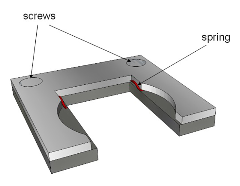
Figure 4: Sample holder. The holder fits to the interior dimensions of the glass cuvette. Two springs (in red) hold the glass slide (described in Figure 3). This holder is then put inside the glass cuvette.
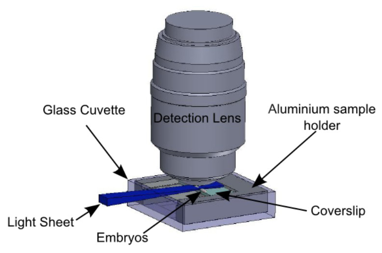
Figure 5: Sample holder in the observation context. Embryos are immobilized on the glass slide according to the protocol summed up in Figure 3. The slide is held by the sample holder described in Figure 4. The sample holder is inserted in the glass cuvette, held by the holder described in Figure 2. The light sheet is horizontal and illuminates the embryos from the side. The detection objective lens is vertical, above the sample.
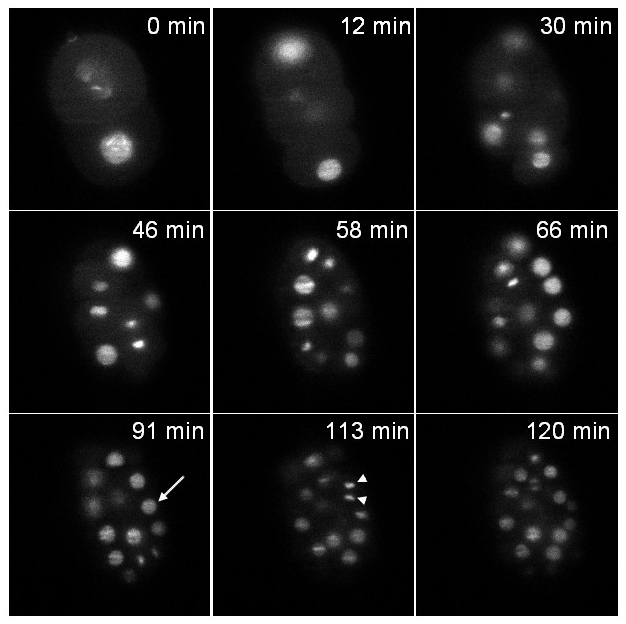
Figure 6: Recording of a C. elegans embryo expressing an histone::GFP fusion. Single plane images of a transgenic embryo expressing an histone::GFP fusion (zuIs178; stIs10024) at different time points. Images extracted from a 3D time-lapse recording: stacks made of 20 slices (distance between slices 1 µm); exposure time per slice: 30 msec; time interval between stacks: 37 sec; total acquisition time: 2 hr. Arrow: interphasic nucleus, arrow head: condensed mitotic chromatin. At t = 0 min the embryo is at the 2-cell stage and at t = 120 min the embryo contains around 70 cells as expected under normal developmental speed (note that only the cells contained in a single plane are visible in the pictures and not all the cells of the embryo). The power of illumination was 30 µW at 488 nm (measured at the exit of the illumination objective). Please click here to view this video.
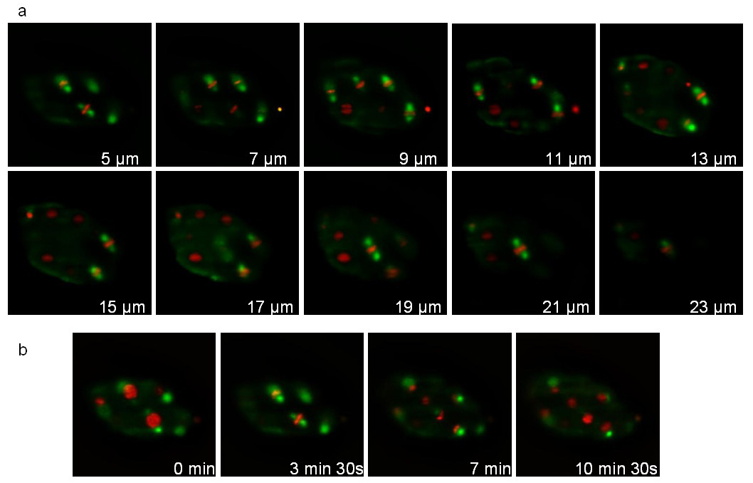
Figure 7: Recording of a C. elegans embryo expressing a Tubulin::GFP fusion and an Histone::mCherry fusion. Images extracted from a 3D time-lapse recording of a C. elegans embryo expressing a Tubulin::GFP fusion (ruIs57) and an Histone::mCherry fusion (itIs37 ; stIs10226). Recording conditions: acquisition of a stack of 20 slices (distance between slices 1 µm) every 105 sec; total acquisition time: 16 min; exposure time: 200 msec for each channel. Panel a shows 10 slices of the same stack. Panel b shows the same slice every 210 sec. The power of illumination was 30 µW and 300 µW, for 488 and 561 nm lasers, respectively (measured at the exit of the illumination objective). Please click here to view this video.
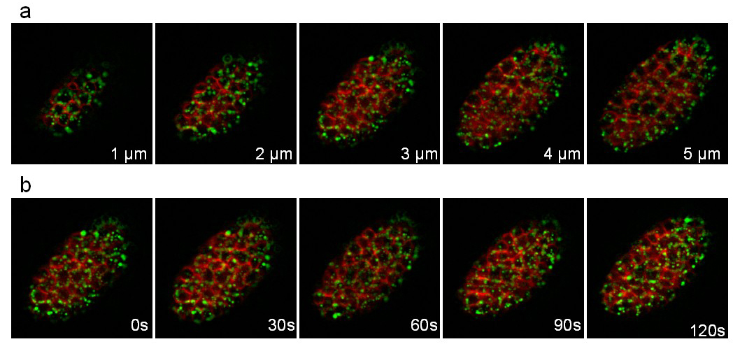
Figure 8: Recording of a C. elegans embryo expressing a VIT-2::GFP fusion and a membrane-targeted mCherry. Images extracted from a 3D time-lapse recording of a C. elegans embryo expressing a VIT-2::GFP fusion (pwIs23) and a membrane-targeted mCherry (ltIs44). Recording conditions: acquisition of a stack of 10 slices (distance between slices 1 µm) every 30 sec; total acquisition time: 25 min; exposure time per channel: 200 msec. Panel a shows the 5 first slices of the same stack. Panel b shows the same slice every 30sec. Please click here to view this video.
Discussion
This protocol describes an easy setup of light sheet microscopy for di vivo imaging of C. elegans embryos. The optical elements necessary to create and align the light sheet, including lasers, beam expander, collimation and focusing lenses, can be easily mounted on an optical bench. In combination with an upright microscope for the detection path and the camera, this provides a simple solution to setup a light sheet microscope.
This geometry makes the sample environment simple. The living specimen is placed in a glass cuvette, which is held, positioned and moved by a small set of mechanical pieces. As sheet illumination microscopy is a wide field technique with sectioning capability, only a single axis motorized movement is required for 3D imaging. This limits the requirement of synchronization to a single scanning element and facilitates software development. Compared to iSPIM6 our upright geometry allows the use of high NA objective lens for detection. Compared to SPIM setups with objective lenses in the horizontal plane the mounting of sample and the imaging of a series of embryos are easier. Altogether, the implementation of this technique is straightforward and can be achieved with little expertise in optics. This is a cheaper alternative to confocal microscopes with the advantages of a higher speed and reduced phototoxicity but drawback of a lower axial resolution.
We also developed an easy and reproducible way to mount C. elegans embryos for in vivo imaging using this system. The mounting procedure is fast (15 min) and is suitable for everyday experiments. For C. elegans imaging, the advantages of this simple setup are at least two-folds: (i) in toto imaging is possible without rotation and thus 3D reconstruction is straightforward; (ii) sample mounting is easy and multiple embryos can be sequentially imaged on the same slide. We showed examples of time-lapse movies with sufficient temporal resolution to observe cell divisions and cell shape changes. The power of light sheet microscopy to study C. elegans development has also been recently illustrated by others6, 7, 8. Therefore, this technique will be very useful to study the morphogenesis and patterning of the C. elegans embryo.
Can this system also be used to analyse the development of other model organisms? It is important to recognize that the implementation of sheet illumination microscopy for small and transparent organism such as C. elegans is less stringent than for larger organisms such as Drosophila embryos. In toto imaging of Drosophila normally requires rotation and multi-view reconstructions9, 10. Excitation from two sides with collinear excitation objective lenses can also reduced the shadow effects caused by the attenuation of light11. Yet, the setup presented here is still adapted to image one side of the Drosophila embryos, with low bleaching and low photoxicity. This setup could also be useful to image small and transparent embryos such as ascidians or zebrafish.
Divulgazioni
The authors have nothing to disclose.
Acknowledgements
We thank all the members of the Lenne and Bertrand labs, in particular Olivier Blanc for software development and Jérémie Capoulade for discussion. We also thank the PICsL-IBDM imaging facility, in particular Claude Moretti and Brice Detailleur for technical support.
This work was supported by ATIP grants from CNRS (to P.-F. L. and V.B.), the Labex INFORM grant (to P.-F.L. and V.B.) and a grant from Sanofi-Aventis (to V.B.). We acknowledge France-BioImaging infrastructure supported by the Agence Nationale de la Recherche (ANR-10-INSB-04-01, call "Investissements d'Avenir").
Materials
| SPIM | |||
| Detection | |||
| upright microscope | ZEISS | Axiophot 1 | |
| 100xW objective (NA 1.1, W.D. 2.5mm) | NIKON | ||
| EMCCD back illuminated | ANDOR | DU-885K-CS0-#VP | |
| Illumination | |||
| LASER 488nm / 60mW | TOPTICA | iBeam smart | |
| LASER 405nm / 120mW | TOPTICA | iBeam smart | |
| LASER 561nm / 500mW | COBOLT | JIVE 500 | for time lapse imaging, 50 or 100mW is enough |
| filter Quad line laser rejectionband ZET 405/488/561/638 | AHF | F57-405 | |
| Dichroic 405 | AHF | F38-405 | |
| Dichroic 488 | SEMROCK | Di01-R488 | |
| AOTF | AA | AOTFnC-400.650-TN | |
| mirror | |||
| lens 50mm | THORLABS | telescope 5X | |
| lens 200mm | THORLABS | telescope 5X | |
| periscope | THORLABS | RS99/M | |
| cylindrical lens f=100mm | THORLABS | ACY254-100-A | |
| 10X NA 0,3 | NIKON | ||
| xyz stage | NEWPORT | ||
| Sample | |||
| Bacto Agar | Bectkton Dickinson | 214010 | 5% in water |
| Poly-L-Lysine solution | Sigma | P8920 | |
| Capillaries GC100F-10, 1.0mm oD, 0,58mm ID, 100 mm L | Havard Appartus | 30-0019 | |
| Aspiration tube (mouth pipette) | Dutsher | 55005 | |
| M9 medium: | |||
| KH2PO4 (3g/L) | Any supplier | ||
| Na2HPO4 (6g/L) | Any supplier | ||
| NaCL (5g/L) | Any supplier | ||
| MgSO4 (1mM final) | Any supplier | ||
| cuvette holder | HOME MADE | made by Brice Detailleur | |
| sample holder | HOME MADE | made by Claude Moretti | |
| x stage | NEWPORT | ||
| coverslip 50x20x1mm | MARIENFELD | cut then in 10x20x1mm | |
| piezo electric stage with amplifier/controller | PI | P-622.ZCD / E-625.CR | |
| cuvette 40mmx40mmx10mm | HELLMA | 704.002-OG.40 mm- 10mm high | |
| Diamond Point Glass Marking Pencil | VWR | ||
| Software | |||
| C++ (Qt) home made software | developed by Olivier Blanc and Claire Chardès, available on request. Alternative solutions: micromanager or labview |
Riferimenti
- Huisken, J., Swoger, J., Del Bene, F., Wittbrodt, J., Stelzer, E. H. Optical sectioning deep inside live embryos by selective plane illumination microscopy. Science. 305, 1007-1009 (2004).
- Huisken, J., Stainier, D. Y. Selective plane illumination microscopy techniques in developmental biology. Development. 136, 1963-1975 (2009).
- Reynaud, E. G., Krzic, U., Greger, K., Stelzer, E. H. Light sheet-based fluorescence microscopy: more dimensions, more photons, and less photodamage. HFSP J. 2, 266-275 (2008).
- Sulston, J. E., Schierenberg, E., White, J. G., Thomson, J. N. The embryonic cell lineage of the nematode Caenorhabditis elegans. Dev Biol. 100, 64-119 (1983).
- Hardin, J. Imaging embryonic morphogenesis in C. elegans. Methods Cell Biol. 106, 377-412 (2011).
- Wu, Y., et al. Inverted selective plane illumination microscopy (iSPIM) enables coupled cell identity lineaging and neurodevelopmental imaging in Caenorhabditis elegans. Proc Natl Acad Sci U S A. 108, 17708-17713 (2011).
- Giurumescu, C. A., Kang, S., Planchon, T. A., Betzig, E., Bloomekatz, J., Yelon, D., Cosman, P., Chisholm, A. D. Quantitative semi-automated analysis of morphogenesis with single-cell resolution in complex embryos. Development. 139, 4271-4279 (2012).
- Gao, L., Shao, L., Higgins, C. D., Poulton, J. S., Peifer, M., Davidson, M. W., Wu, X. F. Noninvasive Imaging beyond the Diffraction Limit of 3D Dynamics in Thickly Fluorescent Specimens. Cell. 151, 1370-1385 (2012).
- Krzic, U., Gunther, S., Saunders, T. E., Streichan, S. J., Hufnagel, L. Multiview light-sheet microscope for rapid in toto imaging. Nat Methods. 9, 730-733 (2012).
- Tomer, R., Khairy, K., Amat, F., Keller, P. J. Quantitative high-speed imaging of entire developing embryos with simultaneous multiview light-sheet microscopy. Nat Methods. 9, 755-763 (2012).
- Huisken, J., Stainier, D. Y. Even fluorescence excitation by multidirectional selective plane illumination microscopy (mSPIM). Opt Lett. 32, 2608-2610 (2007).

