In Vitro Reconstitution of Spatial Cell Contact Patterns with Isolated Caenorhabditis elegans Embryo Blastomeres and Adhesive Polystyrene Beads
Summary
Tissue complexities of multicellular systems confound the identification of causal relationship between extracellular cues and individual cellular behaviors. Here, we present a method to study the direct link between contact-dependent cues and division axes using C. elegans embryo blastomeres and adhesive polystyrene beads.
Abstract
In multicellular systems, individual cells are surrounded by the various physical and chemical cues coming from neighboring cells and the environment. This tissue complexity confounds the identification of causal link between extrinsic cues and cellular dynamics. A synthetically reconstituted multicellular system overcomes this problem by enabling researchers to test for a specific cue while eliminating others. Here, we present a method to reconstitute cell contact patterns with isolated Caenorhabditis elegans blastomere and adhesive polystyrene beads. The procedures involve eggshell removal, blastomere isolation by disrupting cell-cell adhesion, preparation of adhesive polystyrene beads, and reconstitution of cell-cell or cell-bead contact. Finally, we present the application of this method to investigate the orientation of cellular division axes that contributes to the regulation of spatial cellular patterning and cell fate specification in developing embryos. This robust, reproducible, and versatile in vitro method enables the study of direct relationships between spatial cell contact patterns and cellular responses.
Introduction
During multicellular development, the cellular behaviors (e.g., division axis) of individual cells are specified by various chemical and physical cues. To understand how individual cell interprets this information, and how they regulate multicellular assembly as an emergent property is one of the ultimate goals of morphogenesis studies. The model organism C. elegans has contributed significantly to the understanding of cellular-level regulation of morphogenesis such as cell polarity1, cell division patterning1, cell fate decision2, and tissue-scale regulations such as neuronal wiring3 and organogenesis4,5. Although there are various genetic tools available, tissue engineering methods are limited.
The most successful tissue engineering method in C. elegans study is the classical blastomere isolation6; as C. elegans embryo is surrounded by an eggshell and a permeability barrier7, their removal is one of the main procedures of this method. While this blastomere isolation method enables reconstitution of cell-cell contact in a simplified manner, it does not allow for the elimination of unwanted cues; cell contact still poses both mechanical (e.g., adhesion) and chemical cues, thereby limiting our ability to fully analyze the causal relationship between the cue and cellular behavior.
The method presented in this paper uses carboxylate modified polystyrene beads that can covalently bind to any amine-reactive molecules including proteins as ligands. Particularly, we used an amine-reactive form of Rhodamine Red-X as a ligand to make beads both visually trackable and adhesive to the cell. The carboxyl groups of bead surface and primary amine groups of ligand molecule are coupled by water-soluble carbodiimide 1-ethyl-3-(dimethylaminopropyl) carbodiimide (EDAC)8,9. Obtained adhesive beads allow for the effects of the mechanical cue on cellular dynamics10. We have used this technique to identify mechanical cues required for cell division orientation10.
Protocol
1. Preparation of adhesive polystyrene bead
NOTE: This protocol does not require aseptic technique.
- Weigh 10 mg of carboxylate modified polystyrene beads in a 1.5 mL microcentrifuge tube.
- To wash the beads, add 1 mL of 2-(N-morpholino)ethanesulfonic acid (MES) buffer into the tube. Since MES buffer does not contain phosphate and acetate, which can reduce the reactivity of carbodiimide, it is suitable to use in protein coupling reaction. Vortex the tube to mix the beads.
- Spin the tube for 60 s at 2,000 x g via a benchtop centrifuge.
- Discard the supernatant by carefully pipetting out the buffer.
- Wash the beads again with 1 mL of MES buffer by following steps 1.2-1.4.
- Add 1 mL of MES buffer containing 10 mg of EDAC into the tube to activate the surface carboxyl groups. Vortex the tube to mix the beads.
- Rotate and incubate the tube for 15 min at room temperature.
- Spin down the beads for 60 s at 2,000 x g.
- Discard the supernatant by carefully pipetting out the buffer.
- To wash the beads, add 1 mL of phosphate buffered saline (PBS) into the tube. Vortex the tube to mix the beads.
- Spin down the tube for 60 s at 2,000 x g.
- Discard the supernatant by carefully pipetting out the buffer.
- Wash the beads again with 1 mL of PBS by following steps 1.10-1.12.
- The final concentration of Rhodamine used will depend on the strain being imaged. Prepare 1 mL of 1-, 10-, 100-, and 1000-fold dilution series of Rhodamine Red-X from the 0.65 mM Rhodamine Red-X stock solution.
- Pipette 20 µL of beads into each serial dilution tube.
- Rotate and incubate the tube for 5 min at room temperature.
- Wash the beads twice with 1 mL of PBS by repeating steps 1.10-1.12.
- Add 1 mL of PBS into the tube and store it at 4 °C for up to 6 weeks. Check the fluorescence intensity of the beads under a microscope used for live-imaging. The appropriate concentration of the Rhodamine Red-X succinimidyl ester is dependent on the imaging conditions (Figure 1).
NOTE: Beads without Rhodamine Red-X treatment do not adhere to cell. Rhodamine Red-X serves as fluorescence marker as well as adhesive molecule. The electro static interaction between positively charged Rhodamine Red-X and negatively charged plasma membrane is a putative cause of adhesion.
2. Assembly of mouth pipette
- Cut wide (6.35 mm inner diameter) and narrow (3.175 mm inner diameter) Tygon tubes to about 25 cm and 40 cm in length, respectively (Figure 2).
- Connect the Tygon tubes with a polytetrafluoroethylene (PTFE) filter (0.2 µm pore size) (Figure 2).
- Disassemble a commercially available aspirator tube and attach its capillary holder and mouthpiece to the end of the narrow and wide Tygon tubes, respectively (Figure 2).
NOTE: PTFE filter was used to prevent the inhalation of fumes of hypochlorite solution via mouth pipette.
3. Isolation of embryo blastomere
NOTE: Wear gloves and lab coat to avoid cut and contact with the bleaching solution.
- Hold each end of a microcapillary (capacity; 10 µL) with right and left hand.
- Pull the microcapillary towards both ends to apply tension and bring the center of the capillary over a burner to make two hand-pulled capillaries (Figure 3A).
- Trim the tips of the hand-pulled capillaries with forceps under the dissecting microscope and attach the pulled capillary into a mouth pipetting apparatus (Figure 2). Prepare two types of pipettes. The tip opening sizes for the pipettes should be approximately 2x and 1x the short axis length of C. elegans embryos (30 µm) for the embryo transfer and eggshell removal, respectively Figure 3B-D).
- Pipette 45 μL of egg salt solution onto a well of a multiwell slide (Figure 4A; bottom).
- Place 5-10 adult C. elegans onto a well containing egg salt solution.
- To obtain early C. elegans embryos, cut adults into pieces by positioning two needles to the right and left of C. elegans body and sliding the needles past each other (Figure 4A; upper schematics).
- Pipette 45 μL of hypochlorite solution onto a well next to the well containing egg salt solution (Figure 4B).
- Pipette 45 μL of Shelton's growth medium onto the subsequent three wells next to the well containing hypochlorite solution (Figure 4B).
- Transfer 1-cell stage and early 2-cell stage embryos into the hypochlorite solution by mouth pipetting with the hand-drawn capillary for embryo transfer (Figure 4B).
- Wait for 40–55 s.
- Wash the embryos by transferring the embryos from hypochlorite solution into Shelton's growth medium by mouth pipetting with the hand-drawn capillary for embryo transfer (Figure 4B).
- Wash the embryos again by transferring the embryos into a new well of Shelton's growth medium by mouth pipetting with the hand-drawn capillary for embryo transfer (Figure 4B).
- Transfer the washed embryos into a new well of Shelton's growth medium by mouth pipetting with the hand-drawn capillary for embryo transfer. Using the hand-drawn capillary for eggshell removal, carefully repeat the pipetting (Figure 4C; middle schematics). If the eggshell is successfully removed, the embryonic cells will become more spherical (Figure 4C; right).
- Separate the 2-cell stage embryonic blastomeres by gently and continuously pipetting with the hand-drawn capillary for eggshell removal (Figure 4D).
4. Reconstitution of contact patterns with blastomere and bead
NOTE: Work under the imaging microscope to avoid dissociation of a cell from a bead and to facilitate the timely image acquisition.
- To observe using an inverted microscope, prepare an imaging chamber as in Figure 5.
- Place a coverslip onto a coverslip holder (Figure 5A).
- Tape the edges of the coverslip to stabilize it. The side with tape is the 'back' side (Figure 5A,B).
- Flip the coverslip holder over to the 'front' side and draw a circle on the coverslip with a hydrophobic pen (Figure 5C).
NOTE: Any glass-bottom dish also works, provided the embryos are manipulatable by the mouth pipette.
- Add Shelton's growth medium within the circle drawn by the hydrophobic marker (Figure 5D).
- Transfer the isolated blastomere to the imaging chamber.
- Dispense a small volume of the chemically functionalized beads using the hand-drawn capillary for embryo transfer.
- Control the position of the polystyrene beads by blowing into the hand-drawn capillary until the bead attaches to the isolated blastomere.
- Mount a coverslip to avoid evaporation of medium (Figure 5E). Perform live imaging.
5. Preparation of important reagents
- Egg Salt Solution (10 mL): Combine 235 µL of 5 M NaCl and 240 µL of 2 M KCl with 9525 µL of dH2O.
- Hypochlorite Solution (10 mL): Combine 7.5 mL of Clorox (containing approximately 7.5% sodium hypochlorite) with 2.5 mL of 10 N NaOH (final concentration of sodium hypochlorite is approximately 5.625%).
NOTE: Although many published methods have used chitinase to digest chitinous eggshells, we have adopted a method using hypochlorite solution11. By avoiding the batch-to-batch variations of chitinase activities, we believe this method is more reproducible and cost-effective approach. - 0.81 mM Inulin Solution (40 mL)
- Add 0.2 g of Inulin to 40 mL of dH2O.
- Autoclave to dissolve.
NOTE: Keeps for 1 month at 4 °C.
- 0.5 M MES Buffer (500 mL)
- Dissolve 48.81 g of MES in 400 mL of distilled water (dH2O).
- Adjust pH to 6.0.
- Bring the total volume to 500 mL with dH2O.
- PBS Solution (1 L)
- To make 10-fold PBS solution, dissolve 1 package of PBS premix powder in 1 L of dH2O.
- Combine 100 mL of 10-fold PBS solution with 900 mL of dH2O.
- 5% Polyvinylpyrrolidone (PVP) Solution (4 mL)
- Under sterile conditions, dissolve 0.2 g of PVP in 4 mL of Drosophila Schneider's Medium.
NOTE: Always open Schneider's Medium stock in tissue culture (TC) hood. Keep for 1 month at 4 °C.
- Under sterile conditions, dissolve 0.2 g of PVP in 4 mL of Drosophila Schneider's Medium.
- 0.65 mM Rhodamine Red-X stock solution (2 mL)
- Weigh 1 mg of Rhodamine Red-X.
- Add 2 mL of dimethyl sulfoxide (DMSO) to dissolve.
- Aliquot and store at -20 °C.
- Shelton's Growth Medium (SGM) (10.25 mL)
- Under sterile conditions, combine 8 mL of Drosophila Schneider's Medium, 1 mL of PVP solution, 1 mL of Inulin solution, 1 mL of Basal Medium Eagle (BME) Vitamins, 50 µL of Penicillin-Streptomycin, and 100 µL of Lipid concentrate together.
- Aliquot 325 µL of SGM into 1.5 mL microtubes.
NOTE: Keep for about 1 month at 4 °C. - On the day of blastomere isolation, add 175 µL of Fetal Bovine Serum (FBS) to the SGM (for total volume of 500 µL).
NOTE: Store FBS at -20 °C and thaw it before usage. FBS does not need to be heat killed.
Representative Results
For beads preparation, we determined the optimal amount of Rhodamine Red-X succinimidyl ester for the transgenic strain expressing GFP-myosin II and mCherry-histone (Figure 1A-D). We used mCherry tagged histone as a marker of cell cycle progression. Because both Rhodamine Red-X and mCherry will be illuminated by a 561 nm laser, the optimal intensity of Rhodamine Red-X signal is comparable to that of histone to allow simultaneous imaging of cell and bead. For example, the fluorescence signal from the bead treated with 0.005 µg/mL Rhodamine Red-X succinimidyl ester was too weak to visualize the bead (Figure 1A). On the other hand, the fluorescence signal from the beads treated with 5 µg/mL Rhodamine Red-X succinimidyl ester was too strong to image mCherry-histone (Figure 1D). We determined that 0.5 µg/mL Rhodamine Red-X succinimidyl ester is optimal for this particular transgenic strain (Figure 1C).
Blastomere isolation was performed according to the procedures shown in Figure 4. The following points should be addressed for successful experiments. 1) The media in the well evaporates over time and becomes viscous; this causes the embryos to stick to the glass capillary and other embryos, so a new well with fresh media needs to be used. 2) In the hypochlorite solution, embryos float to the surface. Therefore, lower the magnification of the microscope and focus on the surface of the droplet to ease with the transferring of embryos. 3) The effectiveness of hypochlorite solution may differ. Hence, duration of embryos spend in the hypochlorite solution should be tested for each new batch of hypochlorite solution made. 4) Place the mouth pipette as close to the embryo as possible to minimize the strength used to blow into the pipette, but also not too close so that the embryo is sucked up as well (this is also true when attaching beads). 5) After eggshell removal, embryos become very delicate. Hence, forces exerted on the mouth pipette need to be slightly lowered to prevent embryos from bursting. 6) Prolonged usage of the mouth pipette may dampen the PTFE filter, and 7) 2-cell stage embryos should only be separated when the nucleus has been clearly formed (Figure 4C, left schematics). Compared to cells in intact embryos (Figure 4A; right), cells in embryos without eggshell look rounder (Figure 4C; right). Additionally, after blastomere isolation, the shape of blastomeres become spherical (Figure 4D; right).
To test the effects of physical contact-dependent cue on cell division orientation, we attached Rhodamine Red-X coated beads to AB blastomeres isolated from the 2-cell stage and performed live-imaging (Figure 6, Figure 7). The bead without Rhodamine Red-X treatment did not adhere to the blastomeres, suggesting that the Rhodamine Red-X serves as a both fluorescence marker and adhesive molecule. For the analysis of cell division orientation, we have 3D reconstructed the time-lapse image using the "3D project" function of ImageJ12 (Figure 6A; tilting around Y-axis). To determine the plane containing mitotic spindle (spindle plane), we first identified a plane where two centrosomes were vertically aligned (Figure 6B; 110°): the plane with ± 90° angle of this plane is spindle plane (Figure 6B; -20°). Next, we have measured the angle of spindle (spindle orientation) relative to the cell-bead contact interface (contact orientation) after cytokinesis (Figure 6C). When both daughter cells were attached to the bead, a line that passes both contact sites was used as a contact orientation.
In our previous study, we have identified an anisotropic cell surface myosin flow during the bead-induced AB cell division orientation10. However, it is difficult to measure the intracellular myosin flow as cell moves during oriented division. To perform this, first we have selected the samples with spindle aligned to the imaging plane (xy plane) (Figure 7). Second, Z-stacks were projected using maximum projection method (Figure 7). Third, cell movements were corrected using the subpixel registration algorithm Stack reg plug-in13 of ImageJ with Rigid body option (Figure 7B). By the registration of images, the position of cell was stabled (Figure 7B). Finally, by using Manual tracking plug-in of ImageJ, myosin foci were tracked (Figure 7C). According to the coordinate information, velocities of myosin along division axis, and axis perpendicular to it were calculated within 50 s after the cytokinesis onset.
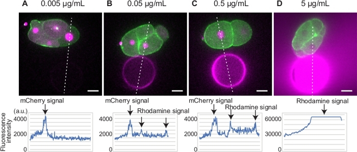
Figure 1: Determination of Rhodamine Red-X concentration. (A-D) Embryos expressing GFP-myosin (green) and mCherry-histone (magenta) were placed in proximity to beads bound with different concentrations of Rhodamine Red-X (magenta). The signal intensities of mCherry and Rhodamine Red-X are plotted along the white dotted lines (bottom graphs). The beads and histone signals were clearly detected for beads treated with 0.5 µg/mL Rhodamine Red-X. Scale bars show 10 µm. Please click here to view a larger version of this figure.
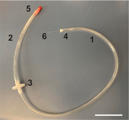
Figure 2: Assembly of mouth pipette. Mouth pipette is assembled by connecting narrow (1) and wide (2) Tygon tubes with a PTFE filter (3). At the end of the narrow and wide Tygon tube, capillary holder (4) and mouth piece (5) were attached, respectively. A hand-drawn glass capillary (6) can be inserted in the capillary holder. Scale bar is 50 mm. Please click here to view a larger version of this figure.
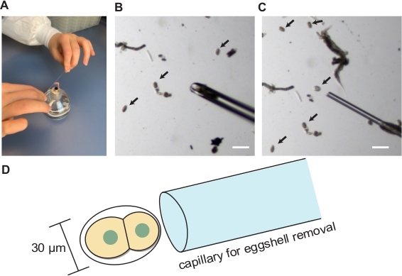
Figure 3: Blastomere isolation. (A) Hand pulling of glass capillary. (B) Hand-drawn glass capillary for embryo transfer. (C) Hand-drawn glass capillary for eggshell removal. (D) Schematics showing the appropriate size of capillary opening for the eggshell removal. Arrows indicate embryos. Scale bars show 100 µm. Please click here to view a larger version of this figure.
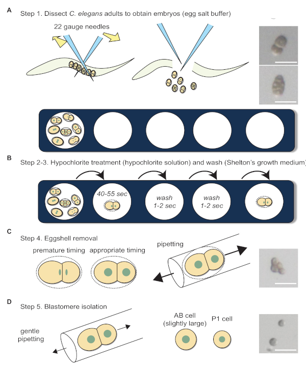
Figure 4: Blastomere isolation workflow. (A) Dissection of adult C. elegans in egg salt buffer to obtain embryos. Photographs show 2-cell and 4-cell stage embryos before eggshell removal. (B) Hypochlorite treatment and washing. (C) Schematics depict the appropriate timing for eggshell removal. Photograph shows a 4-cell stage embryo after eggshell removal. (D) Blastomere separation. Photograph shows a separated 2-cell stage embryo. Sizes of the arrows in C and D indicate the relative forces required during pipetting. Scale bars show 50 µm. Please click here to view a larger version of this figure.
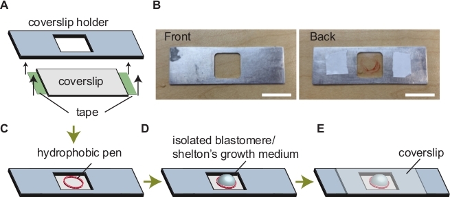
Figure 5: Assembly of imaging chamber. (A) Attaching coverslip to the coverslip holder. (B) Images of a coverslip holder. Coverslip holder before and after assembly is indicated on the left and right, respectively. (C) A circle drawn via a hydrophobic pen. (D) Addition of Shelton's growth medium and sample within the circle. (E) Mounting a coverslip to avoid evaporation. Scale bars show 50 mm. Please click here to view a larger version of this figure.
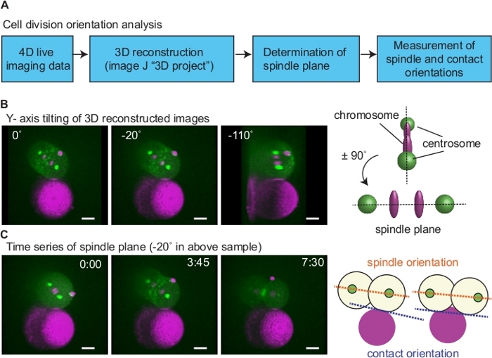
Figure 6: Analysis of cell division orientation. (A) A diagram of cell division orientation analysis. (B) Determination of spindle plane. Left images show an example of a sample. 3D reconstructed 4-D movies were rotated around Y-axis to determine the plane wherein two centrosomes align vertically (right image; right upper schematics). In this example, spindle plane is ± 90° of 110° (middle image; right bottom schematics). (C) Measurement of spindle orientation relative to the cell-bead contact. Using images of the spindle plane, spindle orientation after cytokinesis was determined based on angle between lines connecting two centrosomes (orange dotted lines in the right schematics) and cell contact (blue dotted lines). When both daughter cells were attached to the beads, cell-bead contact orientation was the line that passes both contact sites. Green is myosin and centrosome, magenta is histone and beads. Scale bars are 10 µm. Times are minutes and seconds. Please click here to view a larger version of this figure.
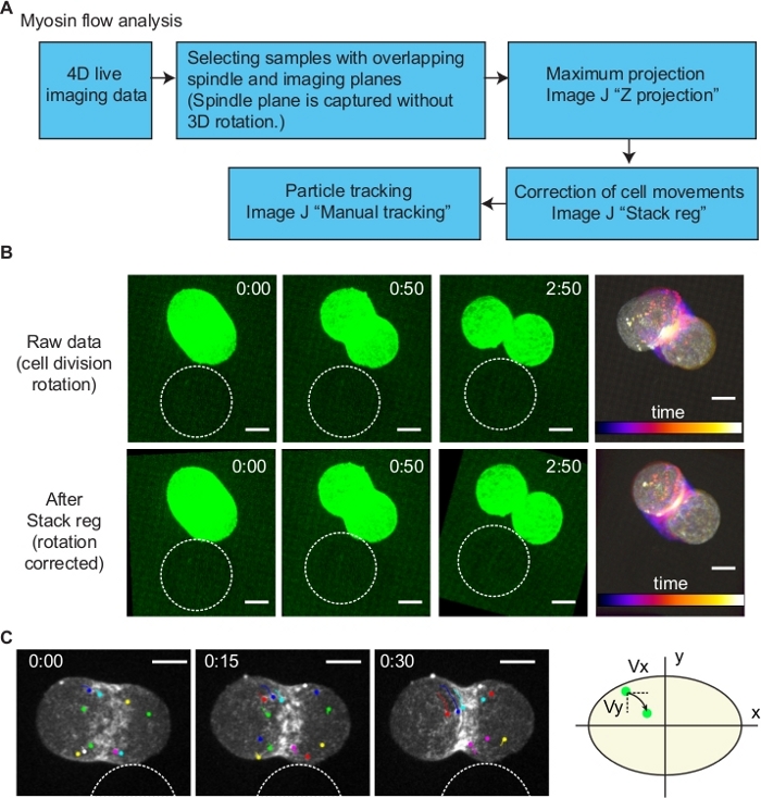
Figure 7: Analysis of myosin flow. (A) A diagram of myosin flow analysis. (B) Correction of cell division orientation. To quantify intracellular myosin flow dynamics, the rotation of dividing cell was corrected using the ImageJ plugin Stack reg (Rigid body option). Upper and bottom images are before and after the Stack reg processing. Right most images show temporal color code of time series. (C) Tracking of myosin foci. Using the images processed by Stack reg, individual myosin foci movements were tracked by ImageJ Manual tracking plugin. Division axis and the axis perpendicular to it were defined as x and y, respectively (right schematics). Myosin flow velocities in x and y axis (Vx and Vy) were measured according to the coordinate information. Scale bars are 10 µm. Times are minutes and seconds. Please click here to view a larger version of this figure.
Discussion
Reconstitution of simplified cell contact patterns will let researchers to test the roles of specific cell contact patterns in different aspects of morphogenesis. We have used this technique to show that cell division axis is controlled by the physical contact with adhesive beads10. As division axis specification is crucial for multicellular development by contributing to morphogenesis14, stem cell division15,16, and tissue homeostasis15,16, this method should be able to illuminate a new mechanism of animal tissue formation.
In addition to cell division orientation, this method has a potential to be a platform to test the relationship between mechanical cues and cell fate. Previous studies reported that mechanical cue controls cell fate specification. Human mesenchymal stem cells differentiate into neuron, adipocyte, skeletal muscle cell, and osteoblast when cultured in substrate with different stiffness17. In response to substrate stiffness, the transcriptional regulators Yes-associated protein (YAP) and TAZ (transcriptional co-activator with PDZ-binding motif) will translocate to nucleus, to regulate cell fate specification18. The method presented in this paper should also be useful to test the role of mechanical cues on cell fate specification, by culturing cell long-term in contact with adhesive beads.
This method has limitations in recapitulating certain mechanical cues observed in vivo. In C. elegans, chitinous eggshell and permeability barrier serve as a physical constrain. Although the removal of eggshell does not affect normal development, removal of both eggshell and permeability barrier results in abnormal pattern formation19. In the absence of eggshell and permeability barrier, cell shape becomes more spherical, suggesting that the pressure between cells and cell-eggshell plays a critical role in cell deformation and patterning. Indeed, cell-cell squeezing forces has been proposed to regulate cell division orientation20. Without having physical constrain and putative pressure among tissues, we expect that this method also cannot recapitulate in vivo cell contact area. As cell contact area is known to affect Notch signaling21, this limitation needs to be further considered when certain mechanical or chemical cue does not work using this in vitro method.
We have so far tested the cell division orientation of isolated AB, P1, EMS, P2, ABa, ABp cells (cells up to 6 cell stages) in our hands10, but the method can be applied to later development as far as individual cell can be isolated. Recent single cell sequencing study has used pronase digestion of worm body to isolate larval cell22. Therefore, potentially one can use pronase treatment to isolate later stage embryonic cells and larval cells.
In this study, we showed the example of interaction between mechanical cue and cell division orientation, but cell-cell communication is also mediated by chemical cues such as Wnt23, Notch24, adhesion coupled receptors25 and so on. Importantly, the beads preparation method presented here can couple the beads with any proteins, thereby allowing the reconstitution of chemical cues. Previous studies have also used Sepharose bead26 and protein-A magnetic bead27 coated with Wnt protein to demonstrate Wnt-dependent developmental processes. However, these beads are not commercially available in various sizes compared to carboxylate modified polystyrene beads. Hence, future research can use the presented method as a platform to test the role of both chemical and physical cues in more tunable manners. Taken together, this method is suited for researchers, who are studying cellular behaviors and responses that result from spatial cell contact patterns and wish to eliminate other cellular cues.
Divulgations
The authors have nothing to disclose.
Acknowledgements
We thank James Priess and Bruce Bowerman for advice and providing C. elegans strains, Don Moerman, Kota Mizumoto, and Life Sciences Institute Imaging Core Facility for sharing equipment and reagents, Aoi Hiroyasu, Lisa Fernando, Min Jee Kim for the maintenance of C. elegans and critical reading of our manuscript. Our work is supported by the Natural Sciences and Engineering Research Council of Canada (NSERC), (RGPIN-2019-04442).
Materials
| 1-(3-Dimethylaminopropyl)-3-ethylcarbodiimide hydrochloride | Alfa Aesar | AAA1080703 | For the bead preparation |
| Aspirator Tube Assembly | Drummond | 21-180-13 | For the blastomere isolation. |
| Caenorhabditis elegans strain: N2, wild-type | Caenorhabditis Genetics Center | N2 | Strain used in this study |
| Caenorhabditis elegans strain: KSG5, genotype: zuIs45; itIs37 | in house | KSG5 | Strain used in this study |
| Calibrated Mircopipets, 10 µL | Drummond | 21-180-13 | For the blastomere isolation |
| Carboxylate-modified polystyrene beads (30 µm diameter) | KISKER Biotech | PPS-30.0COOHP | For the bead preparation |
| CD Lipid Concentrate | Life Technologies | 11905031 | For the blastomere isolation. Work in the tissue culture hood. |
| Clorox | Clorox | N. A. | For the blastomere isolation. Open a new bottle when the hypochlorite treatment does not work well. |
| Coverslip holder | In house | N.A. | For the blastomere isolation. |
| Dissecting microscope: Zeiss Stemi 508 with M stand. Source of light is built-in LED. Magnification of eye piece is 10X. | Carl Zeiss | Stemi 508 | For the blastomere isolation. |
| Fetal Bovine Serum, Qualified One Shot, Canada origin | Gibco | A3160701 | For the blastomere isolation. Work in the tissue culture hood. |
| General Use and Precision Glide Hypodermic Needles, 25 gauge | BD | 14-826AA | For the blastomere isolation |
| Inulin | Alfa Aesar | AAA1842509 | For the blastomere isolation |
| MEM Vitamin Solution (100x) | Gibco | 11120052 | For the blastomere isolation. |
| MES (Fine White Crystals) | Fisher BioReagents | BP300-100 | For the bead preparation |
| Multitest Slide 10 Well | MP Biomedicals | ICN6041805 | For the blastomere isolation |
| PBS, Phosphate Buffered Saline, 10 x Powder | Fisher BioReagents | BP665-1 | For the bead preparation |
| Penicillin-Streptomycin (10,000 U/mL) | Gibco | 15140148 | For the blastomere isolation. |
| Polyvinylpyrrolidone | Fisher BioReagents | BP431-100 | For the blastomere isolation |
| Potassium Chloride | Bioshop | POC888 | For the blastomere isolation |
| Rhodamine Red-X, Succinimidyl Ester, 5-isomer | Molecular Probes | R6160 | For the bead preparation |
| Schneider’s Drosophila Sterile Medium | Gibco | 21720024 | For the blastomere isolation. Work in the tissue culture hood. |
| Sodium Chloride | Bioshop | SOD001 | For the blastomere isolation |
| Sodium Hydroxide Solution, 10 N | Fisher Chemical | SS255-1 | For the blastomere isolation |
| Spinning disk confocal microscope: Yokogawa CSU-X1, Zeiss Axiovert inverted scope, Quant EM 512 camera, 63X NA 1.4 Plan apochromat objective lens. System was controlled by Slidebook 6.0. | Intelligent Imaging Innovation | N.A. | For live-imaging |
| Syringe Filters, PTFE, Non-Sterile | Basix | 13100115 | For the blastomere isolation. |
| Tygon S3 Laboratory Tubing,, Formulation E-3603, Inner diameter 3.175 mm | Saint Gobain Performance Plastics | 89403-862 | For the blastomere isolation. |
| Tygon S3 Laboratory Tubing,, Formulation E-3603, Inner diameter 6.35 mm | Saint Gobain Performance Plastics | 89403-854 | For the blastomere isolation. |
References
- Herman, M. Hermaphrodite cell-fate specification. WormBook. , (2006).
- Rose, L., Gonczy, P. Polarity establishment, asymmetric division and segregation of fate determinants in early C. elegans embryos. WormBook. , (2014).
- White, J. G., Southgate, E., Thomson, J. N., Brenner, S. The structure of the nervous system of the nematode Caenorhabditis elegans. Philosophical Transactions of the Royal Society of London. B, Biological Sciences. 314 (1165), 1 (1986).
- Mango, S. The C. elegans pharynx: a model for organogenesis. WormBook. , (2007).
- McGhee, J. The C. elegans intestine. WormBook. , (2007).
- Edgar, L. G., Goldstein, B. Culture and Manipulation of Embryonic Cells. Methods in Cell Biology. 107, 151-175 (2012).
- Stein, K. K. The C. elegans eggshell. WormBook. , (2018).
- Quash, G., et al. The preparation of latex particles with covalently bound polyamines, IgG and measles agglutinins and their use in visual agglutination tests. Journal of Immunological Methods. 22 (1), 165-174 (1978).
- Miller, J. V., Cuatrecasas, P., Brad, T. E. Purification of tyrosine aminotransferase by affinity chromatography. Biochimica et Biophysica Acta (BBA) – Enzymology. 276 (2), 407-415 (1972).
- Sugioka, K., Bowerman, B. Combinatorial contact cues specify cell division orientation by directing cortical myosin flows. Developmental Cell. 46 (3), 257-270 (2018).
- Park, F. D., Priess, J. R. Establishment of POP-1 asymmetry in early C. elegans embryos. Development. 130 (15), 3547-3556 (2003).
- Schneider, C. A., Rasband, W. S., Eliceiri, K. W. NIH Image to ImageJ: 25 years of image analysis. Nature Methods. 9 (7), 671-675 (2012).
- Thevenaz, P., Ruttimann, U. E., Unser, M. A pyramid approach to subpixel registration based on intensity. IEEE Transactions on Image Processing. 7 (1), 27-41 (1998).
- Gillies, T. E., Cabernard, C. Cell Division Orientation in Animals. Current Biology. 21 (15), 599-609 (2011).
- Poulson, N. D., Lechler, T. Asymmetric cell divisions in the epidermis. International Review of Cell and Molecular Biology. 295, 199-232 (2012).
- Knoblich, J. A. Asymmetric cell division: recent developments and their implications for tumour biology. Nature Reviews Molecular Cell Biology. 11 (12), 849-860 (2010).
- Engler, A. J., Sen, S., Sweeney, H. L., Discher, D. E. Matrix elasticity directs stem cell lineage specification. Cell. 126 (4), 677-689 (2006).
- Dupont, S., et al. Role of YAP/TAZ in mechanotransduction. Nature. 474 (7350), 179-183 (2011).
- Schierenberg, E., Junkersdorf, B. The role of eggshell and underlying vitelline membrane for normal pattern formation in the early C. elegans embryo. Roux’s Archives of Developmental Biology. 202 (1), 10-16 (1992).
- Wang, Z., Wang, D., Li, H., Bao, Z. Cell neighbor determination in the metazoan embryo system. Proceedings of the 8th ACM International Conference on Bioinformatics, Computational Biology, and Health Informatics. , 305-312 (2017).
- Shaya, O., et al. Cell-cell contact area affects notch signaling and notch-dependent patterning. Developmental Cell. 40 (5), 505-511 (2017).
- Cao, J., et al. Comprehensive single cell transcriptional profiling of a multicellular organism. Science. 357 (6352), 661-667 (2017).
- Goldstein, B., Takeshita, H., Mizumoto, K., Sawa, H. Wnt signals can function as positional cues in establishing cell polarity. Developmental Cell. 10 (3), 391-396 (2006).
- Priess, J. R. Notch signaling in the C. elegans embryo. WormBook. , (2005).
- Müller, A., et al. Oriented cell division in the C. elegans embryo is coordinated by G-protein signaling dependent on the adhesion GPCR LAT-1. PLOS Genetics. 11 (10), 1005624 (2015).
- Marston, D. J., Roh, M., Mikels, A. J., Nusse, R., Goldstein, B. Wnt signaling during Caenorhabditis elegans embryonic development. Methods in Molecular Biology. 469, 103-111 (2008).
- Habib, S. J., et al. A localized Wnt signal orients asymmetric stem cell division in vitro. Science. 339 (6126), 1445-1448 (2013).

