Calcium Imaging in Freely Behaving Caenorhabditis elegans with Well-Controlled, Nonlocalized Vibration
Summary
Reported here is a system for calcium imaging in freely behaving Caenorhabditis elegans with well-controlled, nonlocalized vibration. This system allows researchers to evoke nonlocalized vibrations with well-controlled properties at nano-scale displacement and to quantify calcium currents during responses of C. elegans to the vibrations.
Abstract
Nonlocalized mechanical forces, such as vibrations and acoustic waves, influence a wide variety of biological processes from development to homeostasis. Animals cope with these stimuli by modifying their behavior. Understanding the mechanisms underlying such behavioral modification requires quantification of neural activity during the behavior of interest. Here, we report a method for calcium imaging in freely behaving Caenorhabditis elegans with nonlocalized vibration of specific frequency, displacement, and duration. This method allows the production of well-controlled, nonlocalized vibration using an acoustic transducer and quantification of evoked calcium responses at single-cell resolution. As a proof of principle, the calcium response of a single interneuron, AVA, during the escape response of C. elegans to vibration is demonstrated. This system will facilitate understanding of neural mechanisms underlying behavioral responses to mechanical stimuli.
Introduction
Animals are often exposed to nonlocalized mechanical stimuli such as vibrations or acoustic waves1,2. Because these stimuli influence homeostasis, development, and reproduction, animals must modify their behaviors to cope with them3,4,5. However, the neural circuits and mechanisms underlying such behavioral modification are poorly understood.
Mechanosensory behavior in the nematode, Caenorhabditis elegans, is a simple behavioral paradigm, in which worms usually change behavior from forward movement to a backward escape response when they encounter nonlocalized vibration6. The neural circuit underlying this behavior is composed primarily of five sensory neurons, four pairs of interneurons, and several types of motor neurons7,8. Additionally, worms habituate to such mechanical stimuli after spaced training involving repeated stimulation9,10,11. Therefore, this simple behavioral response constitutes an ideal system to investigate neural mechanisms underlying both nonlocalized vibration-evoked behavior and memory. A protocol for calcium imaging in freely behaving worms under the influence of nonlocalized vibrations is illustrated. Compared with previously reported systems, this system is simple in that it does not require an additional camera for tracking; however, it allows us to change the frequency, displacement, and duration of nonlocalized vibration. Because activation of the AVA interneurons induces the backward escape response, worms co-expressing GCaMP, a calcium indicator, and TagRFP, a calcium-insensitive fluorescent protein, under the control of an AVA-specific promoter were used as an example (see Table of Materials for details). The protocol demonstrates the activation of AVA neurons as a worm switches from forward to backward movement. This protocol facilitates understanding the neural circuit mechanism underlying mechanosensory behavior.
Protocol
1. Cultivation of worms until calcium imaging
- Four days before a calcium imaging experiment, transfer two adult ST12 worms to a new nematode growth medium (NGM) plate (Table of Materials) on which Escherichia coli OP50 are streaked in a square pattern (approximately 4 mm x 4 mm) using a cell spreader so that the worm spends most of the time in the bacteria during calcium imaging12.
- Incubate this NGM plate for 4 days at 20 °C in an incubator (Table of Materials).
2. Hardware setup
- Prepare a microscope equipped with a piezoelectric device for stimulation13, a 2x objective lens, a high-speed sCMOS camera, image splitting optics, an x-y motorized stage, an LED light source for excitation, and a computer (Figure 1). Essential specifications of the sCMOS camera include 2560 x 2160 active pixels, 6.5 µm in size, with a 10-tap camera link as an interface option. Key specifications of the X-Y motorized stage include 110 mm x 75 mm travel range, 250 mm/s max velocity, 2,000 mm/s2 max acceleration, and 0.25 µm unidirectional repeatability.
- Turn on the computer and the x-y motorized stage controller.
- Turn on the amplifier and set the Volume adjuster to 10 and the Bass and Treble adjusters to 8.
- To excite GCaMP and TagRFP, turn on the 488 nm and 560 nm lights of the LED light source. Set the gauges of 470 nm and 550 nm of the control pod in the light source to 5% so that the intensity of the LED light is suitable for imaging.
NOTE: At this LED intensity, photobleaching of GCaMP and TagRFP fluorescence does not occur during recording.
3. Software setup for calcium imaging
- Download and install three software packages in Windows: mouse macro software, software for controlling vibration property, software for running tracking software, and software for data analysis (Table of Materials).
- Double click on the tracking software file.
- Push the Run button and wait for 5 min to stabilize the software (Figure 2A).
- Provide the information on exposure time and binning. 0.033 s exposure time with 2 x 2 binning ensures smooth image acquisition (Figure 2B).
NOTE: Only every 10th image acquired is displayed in order to reduce the memory load. - Provide the information for image acquisition (Figure 2C). For example, when 500 images are recorded twice with an interval of 10 s, enter 1,000 in the Images Total box, 500 in the Images box, and 10 in the Interval (s) box.
- Turn on the Acquisition button (Figure 2D).
- Split the fluorescence image using image splitting optics, and the two images (GCaMP channel, 500-525 nm (Figure 2E); TagRFP channel, 584-676 nm (Figure 2F)) are projected onto two halves of the sCMOS camera. Calibrate the coordinates of the GCaMP and TagRFP channels (Figure 2G). Save the software settings.
- Set the directory to output the data file (Figure 2H).
- Turn off the Acquisition button (Figure 2D).
- Double click on mouse macro system software (Figure 3A) and set the vibration properties (Figure 3B). Read the Assay.txt file with the mouse macro system so that the mouse cursor is controlled based on the coordinates and the schedule in that file (Figure 3A). Set the coordinates of the mouse cursor (magenta squares in Figure 3A) and wait time until stimulation after starting the recording (magenta in Figure 3A). Set the frequency and the amplitude values in the software for vibration control (Figure 3B).
4. Preparation of worms for calcium imaging
- Transfer a single worm expressing both GCaMP and TagRFP from the incubated plate to a new fresh NGM plate on which E. coli OP50 has been streaked.
- Attach the NGM plate to the piezoelectric acoustic transducer using transparent adhesive tape (Figure 4). Do not press the plate onto the actuator because this alters the vibration frequency.
5. Calcium imaging under the control of specific vibration properties
- Turn on the Acquisition button (Figure 2D).
- Find the worm under bright light and excitation light (488 nm and 560 nm).
- Set the zoom value of microscopy to 2.5x. The field of view is 1.1 mm x 1.1 mm with a resolution of 2.6 µm/pixel.
- Turn off the bright light and turn on the Homing button (Figure 2I) to track the fluorescent spot of a worm. This homing button starts the movement of the X-Y stage to keep the maximum intensity region of the worm in the middle of the field of view in the TagRFP image.
NOTE: In terms of the flp-18 promoter, the fluorescent intensity of the AVA neurons is strongest and those from other neurons are faint or not detected. Therefore, the low magnification system is not required for tracking and the stage moves throughout the recording. - Ensure that the values of intensity bars in Figure 2E and 2F are approximately 1,000. If they are not, fine-tune the 470 nm and 550 nm gauges of the control pod in the light source.
- Press the Run button in the mouse macro system to allow mouse cursor control according to a schedule described in Figure 3A. This starts to record using the tracking software and stimulate by wave gene software while tracking the worm.
- Check whether the output BMP file is appropriately created.
6. Data analysis
- Create a folder on the desktop and name it CalciumImaging.
- Create a folder inside the CalciumImaging folder and name it CIResult, for the output result files.
- Double click on the DualViewImaging.nb file written in data analysis software for Windows.
- Insert the file path to the CIResult folder (e.g., DirectoryName[/Users/Sugi0911/Desktop/CalciumImaging/CIResult/test.rtf]) (Figure 5).
- Insert the file path to the folder including the BMP file (e.g., SetDirectory[/Users/Sugi0911/Desktop/XXX/]) (Figure 5), in which XXX denotes the folder name including BMP files.
- Push the Shift and Return keys simultaneously to start an automatic analysis. This analysis uses the value of a maximum intensity region of field of view in the TagRFP image (See the legend of Figure 6 for detailed calculation procedure in the program).
- Check whether the following output files are appropriately created in the CIResult folder.
XXX-GCaMP.tif (image file illustrating traces of GCaMP intensities for all images)
XXX-GCaMP.xls (spreadsheet file listing GCaMP intensities in all images)
XXX-TagRFP.tif (image file illustrating traces of intensities of TagRFP for all images)
XXX-TagRFP.xls (spreadsheet file listing TagRFP intensities in all images)
XXX-Ratio.tif (image file illustrating traces of the ratio value for all images)
XXX-Ratio.xls (spreadsheet file listing the ratio value in all images)
Representative Results
Here, a worm expressing both GCaMP and TagRFP under control of the AVA interneuron-specific promoter is used as an example of calcium imaging in freely behaving C. elegans. GCaMP and TagRFP channel data were obtained as a series of images, some of which are shown in Figure 6 and as a movie (Supplemental Movie 1). The displacement of the Petri plate induced by our nonlocalized vibration system (Figure 7) was also quantified. The displacement can be controlled by setting the amplitude value in the software for vibration control (Figure 3B) and the Volume adjuster in the amplifier (Figure 4), whereas the frequency is regulated by setting the frequency value in the software (Figure 4). In the successful experiments, a transient calcium response of AVA neurons was observed upon stimulation with vibrations having a frequency of 630 Hz and a displacement of approximately 4.5 µm for 1 s, indicating that the AVA neuron was activated during a worm's backward response to the nonlocalized stimulation (Figure 6). Baselines of both GCaMP and TagRFP signals also showed that almost no photobleaching occurred during recording.
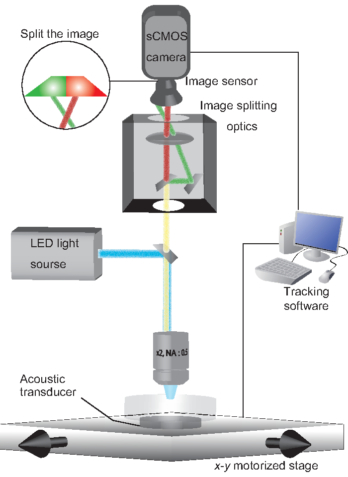
Figure 1: A schematic system configuration. An NGM plate on which a worm freely moves is held on an acoustic transducer. Excitation light (488 nm and 560 nm) is emitted from an LED light source. GCaMP and TagRFP fluorescent emissions are split by image-splitting optics, such that each fluorescent emission is projected onto half of an sCMOS camera. Tracking software controls the x-y motorized stage to track the fluorescent spot of the worm. Please click here to view a larger version of this figure.
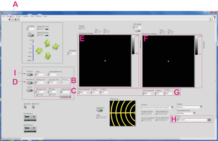
Figure 2: Screenshot of the software for tracking a fluorescent spot of a worm. (A) The Run button for activating the software. (B) Boxes for setting image display cycle, exposure time (s), and binning in each channel. (C) Boxes for providing information on the image acquisition cycle. (D) The Acquisition button to initiate live streaming. (E) GCaMP image. (F) TagRFP image. (G) A panel for calibration coordinates between GCaMP and TagRFP images. (H) Box for setting file path. (I) The Homing button to start worm tracking. Please click here to view a larger version of this figure.
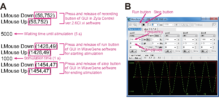
Figure 3: Photo of the mouse macro system and software for controlling vibration. (A) The magenta square indicates the coordinates for the mouse cursor. The meaning of each script line is explained in magenta letters. (B) The GUI (graphical user interface) of software for controlling vibration. Vibration frequency and amplitude values are controlled using this GUI. Please click here to view a larger version of this figure.
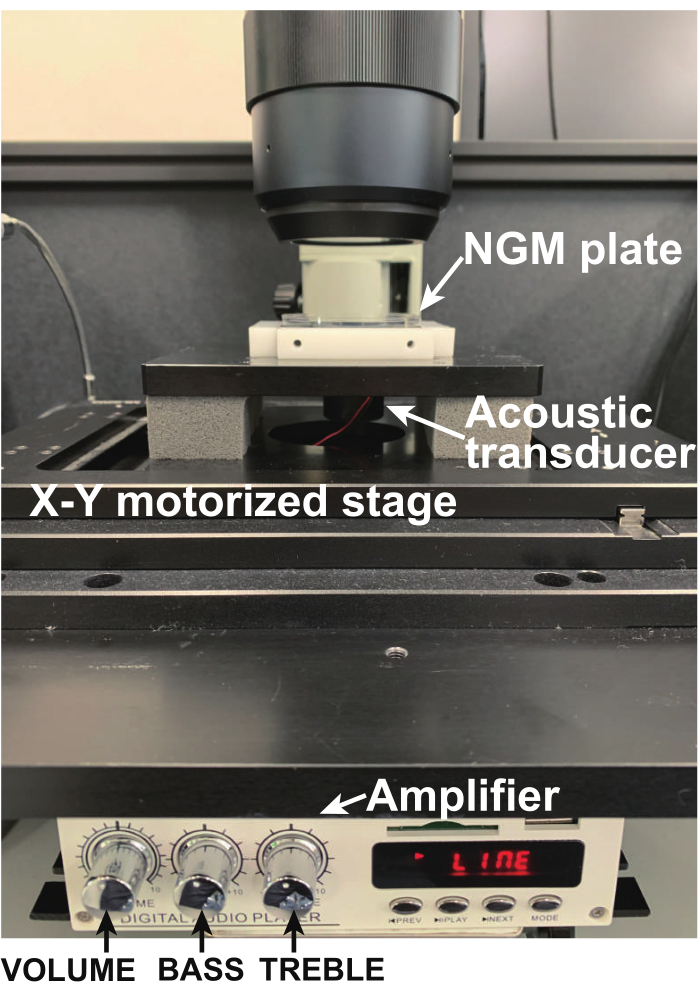
Figure 4: Photo of the NGM plate held on the acoustic transducer using transparent adhesive tape. Only a single worm is moving on the plate. Please click here to view a larger version of this figure.
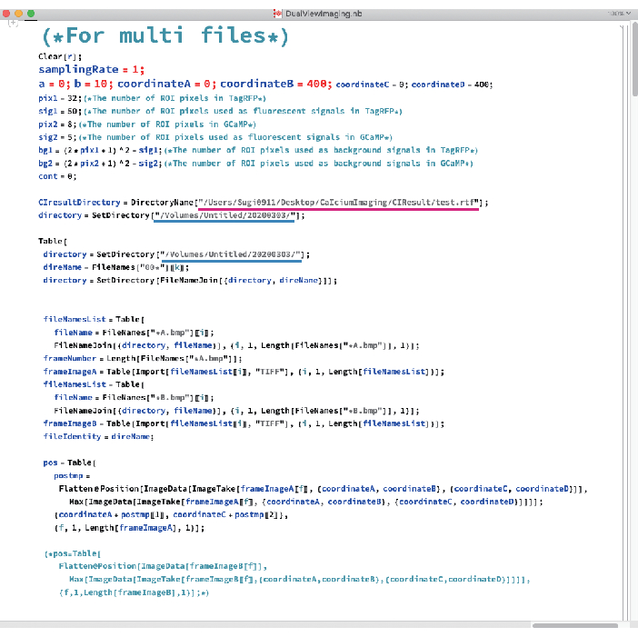
Figure 5: Photo of the data analysis software. Magenta and blue underlines indicate the paths to the CIResult folder and the folder including BMP files, respectively. Please click here to view a larger version of this figure.
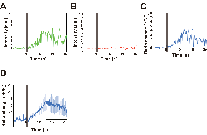
Figure 6: Traces of the intensities of GCaMP (A), and TagRFP (B) fluorescence, and the ratio change (C,D). (A–C) The representative traces for GCaMP signal, TagRFP signal and ratio changes of a single worm. The ratio change is calculated using the DualViewImaging.nb file, as follows. The coordinate in which the intensity of TagRFP fluorescence is maximum after background subtraction is extracted for each image. This TagRFP signal serves to compensate for focus changes caused by the animal's motion. The maximum fluorescence intensity of GCaMP within the extracted coordinate ±10 pixels is calculated as the GCaMP signal intensity for each image. For ratiometry, ((IGCaMP − IGCaMP_BG) − (ITagRFP − ITagRFP_BG)) / (ITagRFP − ITagRFP_BG) is calculated, in which IGCaMP and ITagRFP are the GCaMP and TagRFP signals from the AVA neuron, respectively, and IGCaMP_BG and ITagRFP_BG are the background signals, respectively. This calculation process was applied to all images to quantify the ratio change in a reversal event. The vertical line at 5 s in all traces indicates the stimulation period. (D) The average ratio changes for 15 worms. Error bar indicates SEM. Please click here to view a larger version of this figure.
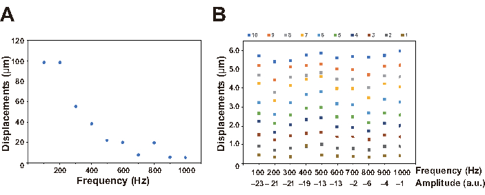
Figure 7: Relationship between parameters. (A) Replacements were measured every 100 Hz using a laser doppler vibrometer, in which the amplitude value in the software and the VOLUME adjuster value in the amplifier were fixed to 0 and 10, respectively. The resonance frequency was observed between 100-200 Hz, which was similar to the value described in the specification of the acoustic transducer. (B) Frequencies and displacements were controlled by the software (range; 100 to 1000 Hz) and the amplifier (range: 1-10), respectively and measured using a laser doppler vibrometer. The amplitude value selected by the software is indicated for each frequency. Please click here to view a larger version of this figure.
Supplementary Movie 1: A representative movie for calcium transients in an AVA interneuron of a freely behaving worm in response to a 630 Hz nonlocalized vibration. Stimulation was evoked 5 s after starting the recording. GFP was also expressed in the intestine of the worm as a co-injection marker for GCaMP. This GFP fluorescence does not affect the signal intensity of GCaMP. The scale bar is also indicated in the first image. The direction of the worm is indicated at the top right after the first image. The Windows media player is suitable for playing the AVI file, but it can also be played using some free downloaded media players, such VLC media player in the Mac. Please click here to download this File.
Discussion
Generally, the quantification of neural activity requires introduction of a probe and/or restraints on animal body movement. However, for studies of mechanosensory behavior, the invasive introduction of a probe and restraints themselves constitute mechanical stimuli. C. elegans provides a system to circumvent these problems, because its features are transparent and because it has a simple, compact neural circuit comprising only 302 neurons. Combining these advantages with the previously developed method of evoking nonlocalized vibrations of nanoscale displacement13, illustrated here is a method for noninvasive calcium imaging of unrestrained C. elegans responding to controlled vibration.
Properties of mechanical stimuli are defined by several parameters, such as frequency, displacement, and duration. Recently, biotremology has emerged as a new research field1. The main purpose of such studies is to understand mechanisms underlying production, dispersion, and reception of mechanical vibrations by organisms, and the influence of those vibrations on behavior. Many animals, including humans, use vibration and acoustic waves to monitor the surrounding environment. For example, scorpions detect prey through substrate-borne vibration14. Therefore, vibration is a tool of communication with the surrounding environment. The method described here can be used to control input parameters and to quantify neural responses at the single-neuron level, leading to a creation of a phase diagram describing the input-output relationship. Based on such phase diagrams, we can gain insights into which parameters affect specific neural circuits, and by what mechanisms animals cope with mechanical vibrations.
Since 200715, several systems have been developed for single-neuron calcium imaging in freely moving C. elegans. These systems have mainly focused on neuronal responses to temperature15,16, odorants16,17, and touch stimuli17. Regarding nonlocalized vibrations, the method of tapping a Petri plate has long been applied for quantifying behavioral responses. However, tapping a Petri plate on a motorized x-y stage caused the fluorescent spot to exit the field of view, leading to failure to track a freely behaving worm. Therefore, the piezoelectric acoustic transducer was embedded, which evokes nonlocalized vibration across the z-axis, in the tracking system. This method allows the performance of reproducible experiments for quantifying neuronal responses to nonlocalized vibration.
The demonstrated methods also offer the possibility of further methodological extension. Since the current protocol can capture responses of only a single neuron in two dimensions, the autofocus system should be equipped in the future to prevent loss of focus. On the other hand, because several volumetric imaging methods have recently been developed using C. elegans18,19,20,21, extension of the approach to volumetric imaging should allow noninvasive quantification of multiple neurons22 or even the whole brain18,19,20,21, in response to vibration having controllable properties. Such a system might be applied to the recently established system to investigate mechanisms underlying collective behavior23. Therefore, further biological applications and extensions of the method likely will enable us to understand neural mechanisms underlying mechanosensory behaviors.
Divulgations
The authors have nothing to disclose.
Acknowledgements
We thank the Caenorhabditis Genetics Center for providing the strains used in this study. This publication was supported by JSPS KAKENHI Grant-in-Aid for Scientific research (B) (Grant no. JP18H02483), on Innovative areas "Science of Soft Robot" project (Grant no. JP18H05474), the PRIME from Japan Agency for Medical Research and Development (grant number 19gm6110022h001), and the Shimadzu foundation.
Materials
| Data anaylsis software | |||
| DualViewImaging.nb | author | For analysis of acquired data | |
| Mathematica12 | Wolfram | For running data anaysis software DualViewImaging | |
| Escherichia coli and C. elegans strains | |||
| E. coli OP50 | Caenorhabditis Genetics Center | OP50 | Food for C. elegans. Uracil auxotroph. E. coli B. |
| lite-1(ce314) strain | Caenorhabditis Genetics Center | KG1180 | Light-insensitive mutant |
| lite-1(ce314) strain expressing NLS-GCaMP-NLS and TagRFP under the control of the AVA-speciric promoter | author | ST12 | lite-1(ce314) mutant carrying the genes expressing NLS-GCaMP5G-NLS (NLS; nuclear localization signal) and TagRFP under the control of the flp-18 promoter as an extrachoromosomal arrays |
| Laser Doppler vibrometer | |||
| Lase Doppler vibrometer | Polytec Japan | IVS-500 | For quantifying frequency and displacement generated by the accoustic transducer |
| Mouse macro system | |||
| Assay.txt | Auteur | Script for temporally and specially controlling mouse cursol in Windows | |
| HiMacroEx | Vector | https://www.vector.co.jp/download/file/winnt/util/fh667310.html | Free download software for controling mouse cursor based on a script |
| Nematode growth media plate | |||
| Agar purified, powder | Nakarai tesque | 01162-15 | For preparation of NGM plates |
| Bacto pepton | Becton Dickinson | 211677 | For preparation of NGM plates |
| Calcium chloride | Wako | 036-00485 | For preparation of NGM plates |
| Cholesterol | Wako | 034-03002 | For preparation of NGM plates |
| di-Photassium hydrogenphosphate | Nakarai tesque | 28727-95 | For preparation of NGM plates |
| LB broth, Lennox | Nakarai tesque | 20066-95 | For culture of E. coli OP50 |
| Magnesium sulfate anhydrous | TGI | M1890 | For preparation of NGM plates |
| Potassium Dihydrogenphosphate | Nakarai tesque | 28720-65 | For preparation of NGM plates |
| Sodium Chloride | Nakarai tesque | 31320-05 | For preparation of NGM plates |
| Petri dishes (60 mm) | Nunc | 150270 | For preparation of NGM plates |
| Nonlocalized vibration device | |||
| Amplifier | LEPY | LP-A7USB | For stimulation with controllable vibration |
| Acoustic transducer | MinebeaMitsumi | LVC25 | For stimulation with controllable vibration |
| WaveGene Ver. 1.5 | Thrive | http://efu.jp.net/soft/wg/down_wg.html | Free download software for controling vibration property |
| Noninvasive calcium imaging | |||
| 2-Channel benchtop 3-phase brushless DC servo controller | Thorlabs | BBD202 | Compatible controller for MLS203-1 stages |
| 479/585 nm BrightLine dual-band bandpass filter | Semrock | FF01-479/585-25 | For acquisition of two channel images (GCaMP and TagRFP) |
| 505/606 nm BrightLine dual-edge standard epi-fluorescence dichroic beamsplitter | Semrock | FF505/606-Di01-25×36 | For acquisition of two channel images (GCaMP and TagRFP) |
| 512/25 nm BrightLine single-band bandpass filter | Semrock | FF01-512/25-25 | For acquisition of two channel images (GCaMP and TagRFP) |
| 630/92 nm BrightLine single-band bandpass filter | Semrock | FF01-630/92-25 | For acquisition of two channel images (GCaMP and TagRFP) |
| Computer | Dell | Precision T7600 | Windows7 with Intel Xeon CPU ES-2630 and 8 GB of RAM |
| High-speed x-y motorized stage | Thorlabs | MLS203-1 | Fast XY scannning stage |
| Image splitting optics | Hamamatsu photonics | A12801-01 | For acquisition of two channel images (GCaMP and TagRFP) generated by W-VIEW GEMINI Image spliting optics |
| LED light source | CoolLED | pE-4000 | For generating 470 nm and 560 nm excitation light |
| Microscope | Olympus | MVX10 | |
| sCMOS camera | Andor | Zyla | |
| x 2 Objective lens | Olympus | MVPLAPO2XC | Working distance 20 mm and numerical aperture 0.5 |
| Plasmid | |||
| pKDK66 plasmid | author | pKDK66 | Co-injection marker |
| pTAK83 plasmid | author | pTAK83 | Plasmid for expression of TagRFP under the control of the flp-18 promoter |
| pTAK144 plasmid | author | pTAK144 | Plasmid for expression of NLS-GCaMP5G-NLS under the control of the flp-18 promoter |
| Tracking software | |||
| homingback.vi | author | SubVi file for tracking a fluoresent spot of a worm through feedback control of sCMOS camera and x-y motorized stage | |
| LabVIEW | National instruments | For running tracking software | |
| Zyla Control ver.2.6CI.vi | author | For tracking a fluoresent spot of a worm through feedback control of sCMOS camera and x-y motorized stage |
References
- Hill, P. S. M., Wessel, A. Biotremology. Current Biology. 26 (5), 187-191 (2016).
- Fettiplace, R., Hackney, C. M. The sensory and motor roles of auditory hair cells. Nature Reviews Neuroscience. 7 (1), 19-29 (2006).
- Vogel, V., Sheetz, M. Local force and geometry sensing regulate cell functions. Nature Reviews Molecular Cell Biology. 7 (4), 265-275 (2006).
- Katta, S., Krieg, M., Goodman, M. B. Feeling force: physical and physiological principles enabling sensory mechanotransduction. Annual Review of Cell and Developmental Biology. 31, 347-371 (2015).
- Orr, A. W., Helmke, B. P., Blackman, B. R., Schwartz, M. A. Mechanisms of mechanotransduction. Developmental Cell. 10 (1), 11-20 (2006).
- Goodman, M. B., Sengupta, P. How Caenorhabditis elegans senses mechanical stress, temperature, and other physical stimuli. Génétique. 212 (1), 25-51 (2019).
- Chalfie, M., et al. The neural circuit for touch sensitivity in Caenorhabditis elegans. The Journal of Neuroscience: The Official Journal of the Society for Neuroscience. 5 (4), 956-964 (1985).
- Wicks, S. R., Rankin, C. H. The integration of antagonistic reflexes revealed by laser ablation of identified neurons determines habituation kinetics of the Caenorhabditis elegans tap withdrawal response. Journal of Comparative Physiology. A Sensory, Neural, and Behavioral Physiology. 179 (5), 675-685 (1996).
- Rankin, C. H., Beck, C. D., Chiba, C. M. Caenorhabditis elegans: a new model system for the study of learning and memory. Behavioural Brain Research. 37 (1), 89-92 (1990).
- Bozorgmehr, T., Ardiel, E. L., McEwan, A. H., Rankin, C. H. Mechanisms of plasticity in a Caenorhabditis elegans mechanosensory circuit. Frontiers in Physiology. 4, 88 (2013).
- Sugi, T., Ohtani, Y., Kumiya, Y., Igarashi, R., Shirakawa, M. High-throughput optical quantification of mechanosensory habituation reveals neurons encoding memory in Caenorhabditis elegans. Proceedings of the National Academy of Sciences of the United States of America. 111 (48), 17236-17241 (2014).
- Stiernagle, T. Maintenance of C. elegans. WormBook. , 1-11 (2006).
- Sugi, T., Okumura, E., Kiso, K., Igarashi, R. Nanoscale mechanical stimulation method for quantifying C. elegans mechanosensory behavior and memory. Analytical Sciences: The International Journal of the Japan Society for Analytical Chemistry. 32 (11), 1159-1164 (2016).
- Brownell, P. H. Compressional and surface waves in sand: used by desert scorpions to locate prey. Science. 197 (4302), 479-482 (1977).
- Clark, D. A., Gabel, C. V., Gabel, H., Samuel, A. D. T. Temporal activity patterns in thermosensory neurons of freely moving Caenorhabditis elegans encode spatial thermal gradients. Journal of Neuroscience. 27 (23), 6083-6090 (2007).
- Tsukada, Y., et al. Reconstruction of spatial thermal gradient encoded in thermosensory neuron AFD in Caenorhabditis elegans. Journal of Neuroscience. 36 (9), 2571-2581 (2016).
- Piggott, B. J., Liu, J., Feng, Z., Wescott, S. A., Xu, X. Z. S. The neural circuits and synaptic mechanisms underlying motor initiation in C. elegans. Cell. 147 (4), 922-933 (2011).
- Nguyen, J. P., et al. Whole-brain calcium imaging with cellular resolution in freely behaving Caenorhabditis elegans. Proceedings of the National Academy of Sciences of the United States of America. 113 (8), 1074-1081 (2016).
- Schrodel, T., Prevedel, R., Aumayr, K., Zimmer, M., Vaziri, A. Brain-wide 3D imaging of neuronal activity in Caenorhabditis elegans with sculpted light. Nature Methods. 10 (10), 1013-1020 (2013).
- Prevedel, R., et al. Simultaneous whole-animal 3D imaging of neuronal activity using light-field microscopy. Nature Methods. 11, 727-730 (2014).
- Nichols, A. L. A., Eichler, T., Latham, R., Zimmer, M. A global brain state underlies C. elegans sleep behavior. Science. 356 (6344), (2017).
- Zheng, M., Cao, P., Yang, J., Xu, X. Z. S., Feng, Z. Calcium imaging of multiple neurons in freely behaving C. elegans. Journal of Neuroscience Methods. 206 (1), 78-82 (2012).
- Sugi, T., Ito, H., Nishimura, M., Nagai, K. H. C. elegans collectively forms dynamical networks. Nature Communications. 10 (1), 1-9 (2019).

