Using Neuron Spiking Activity to Trigger Closed-Loop Stimuli in Neurophysiological Experiments
Summary
This protocol demonstrates how to use an electrophysiological system for closed-loop stimulation triggered by neuronal activity patterns. Sample Matlab code that can be easily modified for different stimulation devices is also provided.
Abstract
Closed-loop neurophysiological systems use patterns of neuronal activity to trigger stimuli, which in turn affect brain activity. Such closed-loop systems are already found in clinical applications, and are important tools for basic brain research. A particularly interesting recent development is the integration of closed-loop approaches with optogenetics, such that specific patterns of neuronal activity can trigger optical stimulation of selected neuronal groups. However, setting up an electrophysiological system for closed-loop experiments can be difficult. Here, a ready-to-apply Matlab code is provided for triggering stimuli based on the activity of single or multiple neurons. This sample code can be easily modified based on individual needs. For instance, it shows how to trigger sound stimuli and how to change it to trigger an external device connected to a PC serial port. The presented protocol is designed to work with a popular neuronal recording system for animal studies (Neuralynx). The implementation of closed-loop stimulation is demonstrated in an awake rat.
Introduction
The goal of this protocol is to demonstrate how to implement closed-loop stimulation in neurophysiological experiments. The typical setup for closed-loop experiments in neuroscience involves triggering stimuli based on the online readout of neuronal activity. This, in turn, causes modifications in the brain activity, thus closing the feedback loop1,2. Such closed-loop experiments provide multiple benefits over standard open-loop setups, especially when combined with optogenetics, which allows researchers to target a specific subset of neurons. For example, Siegle and Wilson used closed-loop manipulations to study the role of theta oscillations in information processing3. They demonstrated that stimulating hippocampal neurons on the falling phase of theta oscillations had different effects on behavior than applying the same stimulation on the rising phase. Closed-loop experiments are also becoming increasingly important in preclinical studies. For instance, multiple epilepsy studies have shown that neuronal stimulation triggered on seizure onset is an effective approach to reduce the severity of seizures4,5,6. Moreover, systems for automated seizure detection and the contingent delivery of therapy7,8 showed significant benefits in epilepsy patients9,10,11,12. Another application area with rapid advancement of closed-loop methodologies is the control of neuroprosthetics with cortical brain–machine interfaces. This is because providing instantaneous feedback to users of prosthetic devices significantly improves accuracy and capability13.
In recent years, several labs have developed custom systems for the simultaneous electrical recording of neuronal activity and delivery of stimuli in a closed-loop system14,15,16,17,18. Although many of those setups have impressive characteristics, it is not always easy to implement them in other labs. This is because the systems often demand experienced technicians to assemble the required electronics and other necessary hardware and software components.
Therefore, in order to facilitate the adoption of closed-loop experiments in neuroscience research, this paper provides a protocol and Matlab code to convert an open-loop electrophysiological recording setup19,20,21,22 into a closed-loop system2,6,23. This protocol is designed to work with the Digital Lynx recording hardware, a popular laboratory system for neuronal population recordings. A typical experiment consists of the following: 1) Recording 5-20 minutes of spiking data; 2) Spike sorting to create neuronal templates; 3) Using these templates to perform online detection of neural activity patterns; and 4) Triggering stimulation or experimental events when user-specified patterns are detected.
Protocol
All procedures described here were performed under an Animal Research Protocol approved by the University of Lethbridge Animal Welfare Committee.
1. Surgery
NOTE: The surgery procedures used to implant probes for neurophysiological recordings have been presented in other publications24,25,26. The exact details of the surgery for closed-loop stimulation depend on the type of recording probes used and the brain areas targeted. In most cases, however, a typical surgery will consist of the following steps.
- Bring to the surgery room a cage with a rat to be implanted with a silicone probe or electrode array to record neuronal activity.
- Anesthetize the rodent with 2-2.5% isoflurane and fix the head in a stereotaxic frame. Ensure that the animal is unconscious during surgery by observing any motoric reaction to mild tactile stimuli25.
- Apply an eye ointment to minimize dryness during the surgery.
- Shave the surgical area and disinfect the skin with 2% chlorhexidine solution and 70% isopropyl alcohol.
- Inject lidocaine (5 mg/kg) under the scalp over the brain area where electrodes will be implanted.
- Make an incision of the scalp over the area of future implant, and use a scalpel and cotton swab to clear the periosteum from the exposed skull25.
- Drill 4-8 holes in the skull for implantation of anchor screws (~0.5 mm) as structural support for the implant25. Attach the screws to the skull by inserting them in the holes and ensure that they are held firmly in place.
- Drill the craniotomy at the specified coordinates, and inset the microdrive/probe implant.
NOTE: The described protocol for closed-loop stimulation will work for any brain region in which the electrodes are inserted. - Fix the microdrive/probe and any required electrical interface connector to the skull using dental acrylic. The amount of dental acrylic should be enough to firmly attach the implant, but it should not come in contact with the surrounding soft tissue25.
- After surgery, closely monitor the animal until it has regained sufficient consciousness to maintain sternal recumbency25. For the subsequent 3 days, administer subcutaneously an analgesic (e.g. Metacam, 1 mg/kg), and an antibiotic to prevent infection (e.g. enrofloxacin, 10 mg/kg).
NOTE: Animals are typically left to recover from surgery for one week prior to any testing or recording.
2. Software installation
NOTE: This was tested on Windows 10, 64 bit version.
- Install data acquisition and processing software.
- Install the data acquisition system Cheetah 6.4 (https://neuralynx.com/software/category/sw-acquisition-control), which includes libraries to interact with the Cheetah Acquisition System.
- Install SpikeSort3D (https://neuralynx.com/software/spikesort-3d) or any other software that uses KlustaKwik27 for spike sorting. The online detection software uses the cluster definitions from the KlustaKwik engine. This software may run on the same computer, or it may run on separate computers that are on the same network.
- Install the NetComDevelopmentPackage (https://github.com/leomol/cheetah-interface/blob/master/NetComDevelopmentPackage_v3.1.0), which can be also downloaded from https://neuralynx.com/software/netcom-development-package.
- Install Matlab (https://www.mathworks.com/downloads/; code was tested on Matlab version R2018a). Make sure that Matlab is enabled in the Windows firewall. Normally a pop-up will come up during the first connection.
- Log in to a Matlab account. Choose the licence. Choose the version. Choose the operating system.
- Download the following library for online event triggering from: https://github.com/leomol/cheetah-interface and extract files to the computer’s ‘Documents/Matlab’ folder. A copy of the code is provided in the accompanying Supplemental Materials.
3. Initial data acquisition
- Start data acquisition using Cheetah software.
- Record a few minutes of spiking data to populate template waveforms.
- Stop the data acquisition and perform spike sorting on the recorded data.
- Open SpikeSort3D, click File | Menu | Load Spike File, and select a spike file from the folder with recorded data.
- Click Cluster Menu and then Autocluster using KlustaKwik, leaving the default settings and click Run.
4. Closed-loop experiment
- Resume data acquisition in Cheetah.
- Open Matlab.
- Open ClosedLoop.m and click on Run. Alternatively, in the Matlab command window, execute ClosedLoop(). Ensure that ClosedLoop.m is on the Matlab path. If the user wants to employ a custom function to call on every trigger, execute ClosedLoop(‘-callback’, customFunction) instead, where customFunction is a handle to that function.
- Load the spike information defined on the initial recording by clicking on Load, browsing to the recording folder, and selecting one of the spiking data files (.ntt, .nse).
- Select one or multiple neurons that will trigger stimulation by clicking the checkbox under the plotted waveforms.
- Define the minimum number of neurons that will trigger stimulation by typing an integer in the “min matches” text box; and define the time window in which spikes matching different waveforms are considered co-active by typing a number in the “window” text box.
- Click Send to start. This will begin online triggering of events (tones as default) based on spiking activity of selected neurons.
Representative Results
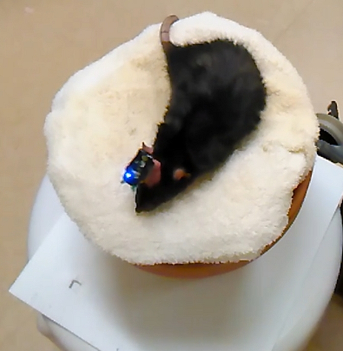
Fisher-Brown Norway rats born and raised on-site were habituated to handling for two weeks prior to the experiment. A recording drive was surgically implanted, similar to methods described previously28,29,30,31,32,33,34. The neuronal signals were recorded at 32 kHz with a digital acquisition system. Neuronal signals were first amplified with a unity gain wireless head-stage, then amplified with a gain of 1000, and band pass filtered between 600 and 6,000 Hz. Neuronal spikes exceeding a manually set amplitude threshold (typically 48-60 µV) were automatically saved, and then sorted into distinct clusters. Thus, each cluster presumably corresponds to spikes from a different neuron27. For this protocol demonstration, the rat was resting on a flowerpot, which was a familiar resting place during breaks in behavioral experiments (Figure 1).
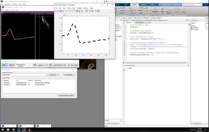
A representative screenshot from the recording computer is shown in Figure 2. It shows the simultaneous running of the recording software (left) and the Matlab program, which displays spike waveforms acquired in real time. This Matlab script is included in the Supplemental Materials. When spikes from predefined triggering clusters are detected, the waveforms are displayed with a bold dashed line in the Matlab figure window (Figure 2), and it triggers a tone, providing a closed-loop system. This closed-loop experimental setup allows, for example, to study neuroplasticity, where one can test if pairing neuronal activity with an external stimuli (tone) can affect the receptive fields of those neurons.

Figure 1: Photograph of a rat with the wireless head-stage (board with pre-amplifiers and a blue LED) attached to an implanted silicone probe. The probe is positioned under the dental acrylic (pink material) and is not visible. Please click here to view a larger version of this figure.

Figure 2: Screenshot of the recording and closed-loop software. Leftward panels are windows that are part of the Cheetah recording system used for visualizing and controlling the data acquisition. The window on the right side of the screen shows a Matlab session running the described software. The middle window shows the waveform of an online detected spike matching a pre-defined template. Spikes belonging to that cluster were used to trigger sound in the presented video. Please click here to view a larger version of this figure.

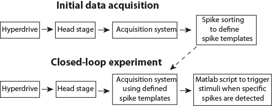
Figure 3: Schematic pipeline for the data flow. Please click here to view a larger version of this figure.

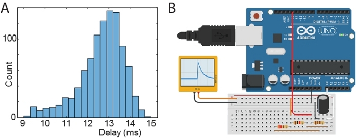
Figure 4: Test of stimulus latency. (A) Histogram of delays between time of generating an artificial spike and time of triggered signal. (B) Schematic of a microprocessor board setup to generate artificial spike waveforms. The black and orange connections output an RC like waveform (ranging from 0 to 810 mV) and it is connected to the head-stage via a “signal-mouse” interface that reduces the voltage to 810 µV. Components plugged in the same column of the breadboard are connected (resistors: 110 Ohm; 220 Ohm; 1000 Ohm; capacitor: 10 µF). The Arduino was connected to a PC via USB/UART, which triggered Arduino spikes and received back signals from both the Arduino circuit and the acquisition software API. The Arduino was instructed to generate 1000 spikes. Please click here to view a larger version of this figure.
Supplemental File 1: Matlab Scripts. Please click here to view this file (Right click to download).
Discussion
The protocol described here, shows how to use a standard neurophysiological recording system to perform closed-loop stimulation. This protocol allows neuroscientists with limited expertise in computer science to rapidly implement a variety of closed-loop experiments with little cost. Such experiments are often necessary to study causal interactions in the brain.
After preparing an animal and installing the software (Steps 1 & 2), the closed-loop experiment consists of two separate stages. First, initial data acquisition (Step 3) to collect data to define templates corresponding to activity of single neurons (i.e., spike sorting; Step 3.5). Secondly, the closed-loop stimulation, where newly recorded spikes will be automatically assigned to predefined clusters in real time and trigger stimulation if spikes form specified neurons are detected (Step 4). The presented Matlab scripts (see Supplemental Materials) demonstrate the triggering of different stimuli based on the activity of a single neuron, and on the activity of multiple selected neurons. The latter is a particularly important option, because neurons are believed to process information as an assembly (e.g., packets35,36). Triggering stimuli based on neuronal population patterns may thus be a key tool for answering a wide range of research questions. The data flow during closed-loop control is illustrated in Figure 3.
In this protocol demonstration, a 3 kHz tone stimuli was used. This pure tone can be replaced by an arbitrary sound waveform by changing the variable “tone0”. Also, note that instead of a speaker, many other devices could be connected to the computer’s audio output to trigger a stimulation. For example, the audio output was used to drive a vibration motor to deliver low frequency (20 Hz) tactile stimuli22. Alternatively, the Matlab code could be used to send a TTL signal to a device connected to a computer serial port. This can be accomplished by replacing the ‘sound()’ command with the following code: obj=serial(‘COM1’); fopen(obj); obj.RequestToSend = ‘on’. A sample implementation of this method is provided in the Supplemental Materials (see pulse.m). Similarly, Matlab could be used to send signals to external devices through a USB port. Thus, the code presented here allows users to send closed-loop triggers in a variety of ways to multiple devices.
Tests showed that the time delay between a neuronal spike and the trigger signal is about 13 ms (min 9 ms; max 15 ms). The distribution of time delays is illustrated in Figure 4A. For this latency tests, an Arduino was used to send an artificial spike to the acquisition system (via the head-stage). The delay was recorded as the time between the spike and the trigger signal from the acquisition PC running the closed-loop Matlab script. The schematic of the Arduino setup to generate spikes is shown in Figure 4B.
The approach presented here is implemented in software, and thus may not be able to deliver stimuli with temporal accuracy of systems with dedicated hardware. For example, TDT (Tucker-Davis Technologies) offers systems for spike triggered stimulation which can deliver stimuli within milliseconds. However, the advantage of the Matlab solution presented here is its low cost for users who own Cheetah recording hardware, its flexibility in defining the activity patterns to trigger stimuli, and its flexibility in defining neuronal templates. Moreover, single millisecond precision is not required in many experiments, so the implementation ease of this approach could offer a major advantage.
Disclosures
The authors have nothing to disclose.
Acknowledgements
This work was supported by NSERC Discovery grants to AL and AG.
Materials
| Baytril | Bayer, Mississauga, CA | DIN 02169428 | antibiotic; 50 mg/mL |
| Cheetah 6.4 | NeuraLynx, Tucson, AZ | 6.4.0.beta | Software interfaces for data acquisition |
| Digital Lynx 4SX | NeuraLynx, Tucson, AZ | 4SX | recording equipment |
| Headstage transmitter | TBSI | B10-3163-GK | transmits the neural signal to the receiver |
| Isoflurane | Fresenius Kabi, Toronto, CA | DIN 02237518 | inhalation anesthetic |
| Jet Denture Powder & Liqud | Lang Dental, Wheeling, US | 1230 | dental acrylic |
| Lacri-Lube | Allergan, Markham, CA | DIN 00210889 | eye ointment |
| Lido-2 | Rafter 8, Calgary | DIN 00654639 | local anesthetic; 20 mg/mL |
| Matlab | Mathworks | R2018b | software for signal processing and triggering external events |
| Metacam | Boehringer, Ingelheim, DE | DIN 02240463 | analgesic; 5 mg/mL |
| Netcom | NeuraLynx | v1 | Application Programming Interface (API) that communicates with Cheetah |
| Silicone probe | Cambridge Neurotech | ASSY-156-DBC2 | implanted device |
| SpikeSort 3D | NeuraLynx, Tucson, AZ | SS3D | spike waveform-to-cell classification tools |
| Wireless Radio Receiver | TBSI | 911-1062-00 | transmits the neural signal to the Digital Lynx |
References
- Grosenick, L., Marshel, J. H., Deisseroth, K. Closed-loop and activity-guided optogenetic control. Neuron. 86 (1), 106-139 (2015).
- Armstrong, C., Krook-Magnuson, E., Oijala, M., Soltesz, I. Closed-loop optogenetic intervention in mice. Nature Protocols. 8 (8), 1475-1493 (2013).
- Siegle, J. H., Wilson, M. A. Enhancement of encoding and retrieval functions through theta phase-specific manipulation of hippocampus. Elife. 3, 03061 (2014).
- Paz, J. T., et al. Closed-loop optogenetic control of thalamus as a tool for interrupting seizures after cortical injury. Nature neuroscience. 16 (1), 64-70 (2013).
- Krook-Magnuson, E., Armstrong, C., Oijala, M., Soltesz, I. On-demand optogenetic control of spontaneous seizures in temporal lobe epilepsy. Nature Communications. 4, 1376 (2013).
- Berényi, A., Belluscio, M., Mao, D., Buzsáki, G. Closed-loop control of epilepsy by transcranial electrical stimulation. Science. 337 (6095), 735-737 (2012).
- Peters, T. E., Bhavaraju, N. C., Frei, M. G., Osorio, I. Network system for automated seizure detection and contingent delivery of therapy. Journal of Clinical Neurophysiology. 18 (6), 545-549 (2001).
- Fountas, K. N., Smith, J. . Operative Neuromodulation. , 357-362 (2007).
- Heck, C. N., et al. Two-year seizure reduction in adults with medically intractable partial onset epilepsy treated with responsive neurostimulation: final results of the RNS System Pivotal trial. Epilepsia. 55 (3), 432-441 (2014).
- Osorio, I., et al. Automated seizure abatement in humans using electrical stimulation. Annals of Neurology. 57 (2), 258-268 (2005).
- Sun, F. T., Morrell, M. J., Wharen, R. E. Responsive cortical stimulation for the treatment of epilepsy. Neurotherapeutics. 5 (1), 68-74 (2008).
- Fountas, K. N., et al. Implantation of a closed-loop stimulation in the management of medically refractory focal epilepsy. Stereotactic and Functional Neurosurgery. 83 (4), 153-158 (2005).
- Abbott, A. Neuroprosthetics: In search of the sixth sense. Nature. 442, (2006).
- Venkatraman, S., Elkabany, K., Long, J. D., Yao, Y., Carmena, J. M. A system for neural recording and closed-loop intracortical microstimulation in awake rodents. IEEE Transactions on Biomedical Engineering. 56 (1), 15-22 (2009).
- Nguyen, T. K. T., et al. Closed-loop optical neural stimulation based on a 32-channel low-noise recording system with online spike sorting. Journal of Neural Engineering. 11 (4), 046005 (2014).
- Laxpati, N. G., et al. Real-time in vivo optogenetic neuromodulation and multielectrode electrophysiologic recording with NeuroRighter. Frontiers in Neuroengineering. 7, 40 (2014).
- Su, Y., et al. A wireless 32-channel implantable bidirectional brain machine interface. Sensors. 16 (10), 1582 (2016).
- Ciliberti, D., Kloosterman, F. Falcon: a highly flexible open-source software for closed-loop neuroscience. Journal of Neural Engineering. 14 (4), 045004 (2017).
- Luczak, A., Bartho, P., Harris, K. D. Gating of sensory input by spontaneous cortical activity. The Journal of Neuroscience. 33 (4), 1684-1695 (2013).
- Luczak, A., Barthó, P., Harris, K. D. Spontaneous events outline the realm of possible sensory responses in neocortical populations. Neuron. 62 (3), 413-425 (2009).
- Schjetnan, A. G., Luczak, A. Recording Large-scale Neuronal Ensembles with Silicon Probes in the Anesthetized Rat. Journal of Visualized Experiments. (56), (2011).
- Bermudez Contreras, E. J., et al. Formation and reverberation of sequential neural activity patterns evoked by sensory stimulation are enhanced during cortical desynchronization. Neuron. 79 (3), 555-566 (2013).
- Girardeau, G., Benchenane, K., Wiener, S. I., Buzsáki, G., Zugaro, M. B. Selective suppression of hippocampal ripples impairs spatial memory. Nature Neuroscience. 12 (10), 1222-1223 (2009).
- Schjetnan, A. G. P., Luczak, A. Recording large-scale neuronal ensembles with silicon probes in the anesthetized rat. Journal of Visualized Experiments. (56), (2011).
- Vandecasteele, M., et al. Large-scale recording of neurons by movable silicon probes in behaving rodents. Journal of Visualized Experiments. (61), e3568 (2012).
- Sariev, A., et al. Implantation of Chronic Silicon Probes and Recording of Hippocampal Place Cells in an Enriched Treadmill Apparatus. Journal of Visualized Experiments. (128), e56438 (2017).
- Harris, K. D., Henze, D. A., Csicsvari, J., Hirase, H., Buzsáki, G. Accuracy of tetrode spike separation as determined by simultaneous intracellular and extracellular measurements. Journal of Neurophysiology. 84 (1), 401-414 (2000).
- Jiang, Z., et al. TaiNi: Maximizing research output whilst improving animals’ welfare in neurophysiology experiments. Scientific Reports. 7 (1), 8086 (2017).
- Gao, Z., et al. A cortico-cerebellar loop for motor planning. Nature. 563 (7729), 113 (2018).
- Neumann, A. R., et al. Involvement of fast-spiking cells in ictal sequences during spontaneous seizures in rats with chronic temporal lobe epilepsy. Brain. 140 (9), 2355-2369 (2017).
- Gothard, K. M., Skaggs, W. E., Moore, K. M., McNaughton, B. L. Binding of hippocampal CA1 neural activity to multiple reference frames in a landmark-based navigation task. Journal of Neuroscience. 16 (2), 823-835 (1996).
- McNaughton, B. L. . Google Patents. , (1999).
- Wilber, A. A., et al. Cortical connectivity maps reveal anatomically distinct areas in the parietal cortex of the rat. Frontiers in Neural Circuits. 8, 146 (2015).
- Mashhoori, A., Hashemnia, S., McNaughton, B. L., Euston, D. R., Gruber, A. J. Rat anterior cingulate cortex recalls features of remote reward locations after disfavoured reinforcements. Elife. 7, 29793 (2018).
- Luczak, A., McNaughton, B. L., Harris, K. D. Packet-based communication in the cortex. Nature Reviews Neuroscience. , (2015).
- Luczak, A. . Analysis and Modeling of Coordinated Multi-neuronal Activity. , 163-182 (2015).

