How to Stabilize Protein: Stability Screens for Thermal Shift Assays and Nano Differential Scanning Fluorimetry in the Virus-X Project
Summary
A protocol is presented to rapidly test the thermal stability of proteins in a variety of conditions through thermal shift assays and nano differential scanning fluorimetry. Buffer systems, salts and additives, together comprising three unique stability screens, are assayed with proteins to identify suitable buffers for functional and structural studies.
Abstract
The Horizon2020 Virus-X project was established in 2015 to explore the virosphere of selected extreme biotopes and discover novel viral proteins. To evaluate the potential biotechnical value of these proteins, the analysis of protein structures and functions is a central challenge in this program. The stability of protein sample is essential to provide meaningful assay results and increase the crystallizability of the targets. The thermal shift assay (TSA), a fluorescence-based technique, is established as a popular method for optimizing the conditions for protein stability in high-throughput. In TSAs, the employed fluorophores are extrinsic, environmentally-sensitive dyes. An alternative, similar technique is nano differential scanning fluorimetry (nanoDSF), which relies on protein native fluorescence. We present here a novel osmolyte screen, a 96-condition screen of organic additives designed to guide crystallization trials through preliminary TSA experiments. Together with previously-developed pH and salt screens, the set of three screens provides a comprehensive analysis of protein stability in a wide range of buffer systems and additives. The utility of the screens is demonstrated in the TSA and nanoDSF analysis of lysozyme and Protein X, a target protein of the Virus-X project.
Introduction
Many biotechnologically-useful enzymes originate from viral sources, such as the tobacco etch virus (TEV) protease1 and human rhinovirus type 3C (HRV 3C) protease2. The Horizon2020 Virus-X project (Figure 1)3. The aim of this program is (a) to extend the range of the properties of known enzyme families and (b) to characterize novel enzymes of yet unknown function (Enzyme X). Crystallographic structure determination plays a pivotal role in target protein characterization, in particular in those cases where the protein sequences have evolved beyond recognition4. Protein stability is a key factor in the crystallization process; samples must be conformationally homogenous and structurally sound over a period of time to form high-quality, diffracting crystals. Furthermore, it is essential for activity assays that the proteins exist in their active conformation, which can also be facilitated by a favorable molecular environment.
Despite the development in the technology available to crystallographers, protein crystallization remains a time-consuming and labor-intensive empirical process5. Preliminary biophysical experiments to improve the protein stability in solution give clearly a better starting point for protein crystallization and consume usually only a comparatively small amount of protein sample6,7,8,9. The large number of target proteins to be studied in this project also necessitates scalable, high-throughput stability assays. One of the most popular methods for pre-crystallization biophysical characterization of the proteins is the thermal shift assay (also known as TSA or differential scanning fluorimetry, DSF)10,11.
TSAs employ an environmentally-sensitive fluorescent dye to track the thermal denaturation of protein samples. Many commonly-used dyes have variable fluorescence activity depending on the polarity of their environment, often displaying a high fluorescence output in hydrophobic environments but undergoing rapid quenching in polar environments12. Proteins generally cause pronounced increases in dye fluorescence as their hydrophobic cores become exposed during denaturation, often followed by a decrease in dye fluorescence at very high temperatures as proteins begin to aggregate (Figure 2).
While a hydrophobicity-sensitive dye is often a good choice for a general-use TSA dye, it can be unsuitable for proteins with large, solvent-exposed hydrophobic regions, which often display detrimentally high background fluorescence. Fluorophores with alternative modes of action exist (see Discussion), but it may instead be desirable to track denaturation through intrinsic protein fluorescence with nanoDSF.
Tryptophan residues that are buried in nonpolar regions of a protein fluoresce with an emission maximum of 330 nm. As a protein sample unfolds and these residues become exposed to a polar solvent, their emission maximum undergoes a bathochromic shift to 350 nm13. nanoDSF exploits this shift in emission maximum to probe the unfolding of a protein sample without the need for extrinsic fluorophores14.
Melt curves showing single denaturation steps can be analyzed by fitting data to a Boltzmann sigmoidal model. The temperature at the inflection point of the unfolding transition (Tm) is used as a quantitative measure of protein thermal stability and a benchmark to compare the favorability of different conditions.
Melt curves of the same protein in different conditions sometimes possess a degree of heterogeneity that can make a Boltzmann sigmoidal fitting unfeasible. To discern Tm values from data that deviates from the classic curve topology, numerical methods can be used such as those employed in NAMI, an open-source TSA data analysis program11. Alternative thermodynamic frameworks can also be used to analyze more complex curves with multiple denaturation steps, such as the ProteoPlex methodology15.
The stability screens were designed for use in TSA and nanoDSF experiments to rapidly identify favorable conditions for a target protein (Figure 3, screen compositions are available in the supplementary information). Information gathered with the screens can be used at many stages of the crystallographic pipeline including: sample storage; purification, minimizing yield loss through protein unfolding during the purification process; assay design, reinforcing protein functionality in activity assays with thermally stabilizing buffers and finally crystallization, guiding rationally-designed crystallization trials.
Choosing a suitable buffer system basis for a protein sample is vital; incompatible pH values can lead to the deactivation or denaturation of a protein. However, the presence of co-crystallized buffer molecules resolved in a large number of X-ray crystal structures (Table 1) could also be indicative of a stabilizing effect that is separate to simple pH regulation and instead stems from the chemical features of the buffer molecule.
Formulated using several of Good's buffers17,18,19 alongside other commonly biologically-compatible buffer systems, the pH screen is designed to deconvolute the chemical effect of a buffer molecule on protein stability from the actual pH of the resulting solution. By providing three pH values for each buffer system and incorporating pH value redundancy between different systems, the pH screen can identify both favorable pH values and favorable buffer systems for a target protein.
The salt screen contains commonly laboratory salts as well as chaotropes, chelants, heavy metals and reducing agents. The screen can give a general indication of the affinity of a protein sample to the environments with high ionic strengths, but each subgroup of the compounds can also provide information on the potential structure of a protein. For example, a chelant significantly destabilizing a protein could be indicative of important structural metals within the sample. If the sample is also strongly stabilized by a metal cation within the screen, this can provide a promising starting point for further structural experiments.
Osmolytes are soluble compounds that affect the osmotic properties of their environment. In nature, they can be used as "chemical chaperones", enforcing the folding of disordered proteins and stabilizing them, especially in stress conditions20,21,22. These characteristics make them attractive additives in protein crystallography; usable as cryoprotectants during the crystal harvesting, mounting and storage processes23. Osmolytes' potential use also extends to the purification of proteins. A significant proportion of recombinant proteins expressed in E. coli can be insoluble and difficult to recover in the native state using standard purification methods. Osmolytes can be used to stabilize and salvage proteins from insoluble fractions, increasing purification yields24.
The osmolyte screen was designed using established compounds present in Protein Data Bank entries25 and the Dragon Explorer of Osmoprotection-Associated Pathways (DEOP)26 database and iteratively optimized using standard proteins. The screen is built around eight subclasses of osmolyte: glycerol, sugars and polyols, non-detergent sulfobetaines (NDSBs), betaines and their analogues, organophosphates, dipeptides, amino acids and their derivatives and a final miscellaneous group. Each osmolyte is present in multiple concentrations based on its solubility and effective concentration ranges for comparison.
Protocol
1. Preparation of Protein Sample
- Formulate the stability screens as 500 µL aliquots in 96-well blocks and seal for storage. Transfer 10 µL of each condition of a stability screen into the corresponding well of a 96-well plate using a multi-channel pipette to save time (Figure 4A).
- Prepare 1 mL of an approximately 1 mg mL-1 protein solution in an appropriate buffer system. While the composition of an appropriate buffer varies with each protein sample, a good first buffer to try is 10 mM sodium phosphate with 100 mM NaCl, pH 7.2.
NOTE: Acceptable protein concentrations vary case-by-case, but concentration ranges of 0.5 – 5 mg mL-1 typically produce analyzable curves. Dilute buffers are recommended for use with the stability screens to avoid masking the effects of each condition. Typical buffer compositions are approximately 10 mM buffer with around 100 mM NaCl. - If performing a TSA experiment, add SYPRO Orange dye to the protein sample to a final concentration of 20x. Mix either by inversion or brief vortexing.
- Transfer 10 µL of the protein solution into each well of the 96-well plate prepared in Step 1.1 (Figure 4B).
- Seal and centrifuge the 96-well plate for 2 min at 600 x g to ensure the protein sample and screen component are mixed (Figure 4C).
- Re-seal the stability screen deep well block and store the screen at 4 °C for up to 4 months. Store the salt screen in darkness, as some components are photosensitive.
- If performing a nanoDSF experiment, continue to step 2. If performing a TSA experiment, skip to step 4.
2. Preparing a nanoDSF Experiment
- Ensure that the equipment is clean, paying particular attention to any dust near the sample rack. If the system has a backscattering mirror, clean it using ethanol and a lint-free tissue.
- Open the sample drawer by pressing the Open Drawer button. (Figure 5A).
- Load the capillaries with approximately 10 µL from each well of the 96-well plate by touching one end of the capillary into the solution, then place them into the corresponding capillary holders of the sample rack (Figure 5B). Be careful not to contaminate the middle of the capillaries with fingerprints, etc., as this could interfere with fluorescence readings throughout the experiment.
- Immobilize the capillaries with the magnetic sealing strip (Figure 5C).
3. Programming a nanoDSF Experiment
- Launch a preliminary scan to detect the position and intensity of each capillary by pressing the Start Discovery Scan button in the Discovery Scan tab. Increase or decrease the incident excitation strength from an initial power of 10% until the peak of every capillary scan is between 4,000-12,000 units (Figure 5D).
- To ensure the sample is folded and sufficiently concentrated, an initial melt scan with a steep temperature gradient is recommended. In the Melting Scan tab, program a melt scan by setting the Temperature Slope option to 7.0 °C min-1, Start Temperature to 25 °C and End Temperature to 95 °C, then launch the nanoDSF experiment by pressing the Start Melting button. If the resulting melt curves do not show a detectable inflection point, consider concentrating the sample further or checking if the protein is folded properly.
- Repeat steps 2.1-2.4 to prepare the samples for a full experiment.
- In the Melting Scan tab, program a melt scan by setting the Temperature Slope option to 1.0 °C min-1, Start Temperature to 25 °C and End Temperature to 95 °C, then launch the nanoDSF experiment by pressing the Start Melting button.
4. Performing a TSA Experiment
- Open the sample drawer by firmly pressing the indent on the right-hand side of the drawer. Place the 96-well tray in the RT-PCR system with well A1 to the back-left (Figure 4D).
- Click the New Experiment button to begin setting up a TSA experiment.
- In the Experiment Properties tab, click the Melt Curve option when asked What type of experiment do you want to set up? and the Other option when asked Which reagents do you want to use to detect the target sequence?
- In the Plate Setup/ Define Targets and Samples tab, enter a target name then set Reporter as ROX and Quencher as None.
- In the Plate Setup/ Assign Targets and Samples tab, assign every well of the 96-well plate to the target name entered in the previous step. In the same tab, set Select the dye to use as the passive reference as None.
- In the Run Method tab, delete steps until there is a total of three. Set the first step to 25.0 °C, ramp rate 100%, time 00:05; the second step to 95.0 °C, ramp rate 1%, time 01:00; the third step to 95.0 °C, ramp rate 100%, time 00:05. Choose to collect data using the Collect Data dropdown menu or by pressing the Data Collection icon (Figure 6).
- Set the Reaction Volume Per Well to 20 µL.
- Press the Start Run button to begin the TSA experiment.
5. Data Analysis
- Choose a wavelength to plot a melt curve with. For nanoDSF experiments, the ratio of fluorescence intensities at 330 nm and 350 nm (corresponding to tryptophan in nonpolar and polar environments, respectively)13 is commonly used. For most TSAs, the dye emission maximum is suitable for melt curve plotting (the emission maximum of SYPRO Orange is 569 nm)12.
- Calculate the Tm values of each condition by determining the inflection point(s) of each melt curve. Most nanoDSF systems automatically calculate Tm values by numerical differentiation of melt curves after data acquisition. If the software used does not automatically calculate Tm values, free, alternative GUI-driven software such as NAMI11 can automate data analysis and downstream processing, giving the option to produce a heatmap summarizing Tm values for the entire 96-well experiment (the accompanying reference provides guidance and resources for data processing with NAMI).
- Compare Tm values of all conditions surveyed. The stability screens contain two wells in each screen (A1 and A2) that contain only water. Taking the water-only values as a benchmark allows calculation of ΔTm values, addressing systematic errors and allowing easy comparison of stabilizing effects. Higher Tm values indicate thermally stabilizing conditions which are recommended for downstream use. Promising conditions often show a concentration dependence in their stabilization.
Representative Results
Lysozyme was assayed with the stability screens and Protein X, a target protein in the Virus-X project, was assayed with the osmolyte screen. Both proteins generally produced melt curves with clearly-defined denaturation transitions in both TSA and nanoDSF experiments (see accompanying figures for representative curves). In a few cases where the samples that did not produce interpretable curves with a defined denaturation transition were interpreted as denatured and not included in Tm comparisons.
Figure 7 shows sample results from the salt screen, exemplifying the thermally-stabilising properties of ammonium chloride towards lysozyme. Concentration dependencies such as that shown above are often indicative of promising conditions, but it can be useful to compare the results of increasing ion concentration with several different salts to see if thermal stabilisation generally arises from an increase in buffer ionic strength or if the presence of specific ions confers additional stability.
Comparison of Tm values of lysozyme with the pH screen (Figure 8) reveals two pieces of information. Firstly, there is a general trend of increasing stability with decreasing pH values. Secondly, the range of Tm values obtained using different buffer systems with identical pH values can be significant.
Data in Figure 8 suggests that the agreement between TSA and nanoDSF in this experiment is generally good, but nanoDSF shows a tendency to identify slightly higher Tm values and slightly larger Tm shifts than TSA. However, some wells with pH values above 8.5 show large discrepancies between Tm values obtained from TSA and nanoDSF. Differences could potentially be attributed to the denaturation mechanism of the protein at different pH values; for example, a hydrophobicity-sensitive dye could give a comparatively low Tm reading if hydrophobic regions of a protein become exposed to solvent significantly faster than the environment of tryptophan residues changes in polarity.
Figure 9 shows a heatmap of Tm values obtained with lysozyme using the osmolyte screen. Conditions with the highest Tm increases compared to the control wells (wells A1 and A2, containing deionized water) are colored dark blue. Especially stabilizing conditions identified in Figure 9 include glycerol, 1 M D-sorbitol, 100 mM hypotaurine and 10 mM Ala-Gly (wells A4-A6, A9, E7 and F8, respectively).
Figure 10 shows a heatmap of Tm values obtained with Protein X. TSA and nanoDSF experiments with the Osmolyte screen reveal that the majority of osmolytes tested give either a minor increase in Tm (within 1 °C) or have a detrimental effect on Protein X's stability. In particular, dipicolinic acid at a concentration of 10 mM (well D1) appears to denature the sample at room temperature. The TSA and nanoDSF results quickly identify dipicolinic acid as an incompatible additive for Protein X which should be avoided when working with the protein. Nevertheless, high concentrations of D-sorbitol and arabinose (wells A9 and B9, both at 1 M) as well as glycerol and TMAO (wells A4-A6 and E1, respectively) were identified as thermally-stabilizing.
For lysozyme, combinations of conditions yielding the highest Tm values from each stability screen were tested to probe for a synergistic combined effect. Figure 11 shows a general increase in Tm values as more components of the buffer system (pH, salt and osmolyte) are added. In the case of MES, ammonium sulphate and D-sorbitol, a Tm increase as large as 10 °C can be observed when all components are present compared to MES alone. Figure 11 shows that a noticeable synergistic effect can occur when individual components of a buffer are optimized and combined with the stability screens.
On a more general note, Figure 11 also illustrates the magnitude of ΔTm values that can be observed in TSA and nanoDSF experiments. The magnitude of ΔTm achievable varies significantly based on the protein system, but any ΔTm value around and above 5 °C is often indicative of a beneficial stabilizing effect.
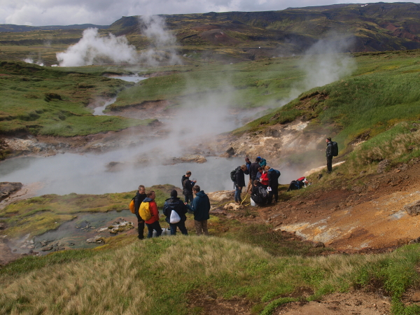
Figure 1: Bioprospecting. Sample collection from an extreme environment in the Virus-X Project. Please click here to view a larger version of this figure.
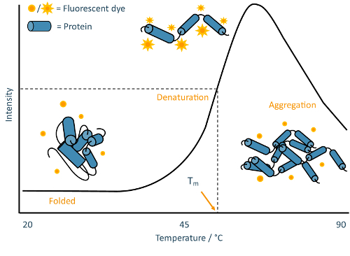
Figure 2: TSA schematic. Annotated example of a typical melt curve obtained from a TSA experiment. This curve is characteristic of classic "two-state" protein unfolding, where the sample population transitions from folded to denatured without detectable partially-folded intermediates. Please click here to view a larger version of this figure.
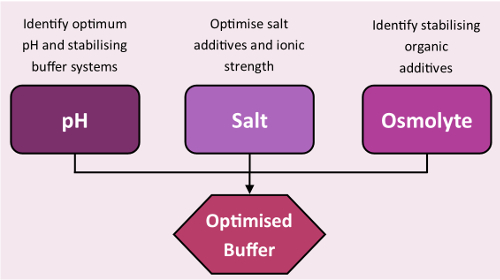
Figure 3: Stability screens workflow. Standard workflow of buffer optimization using the stability screens. Please click here to view a larger version of this figure.
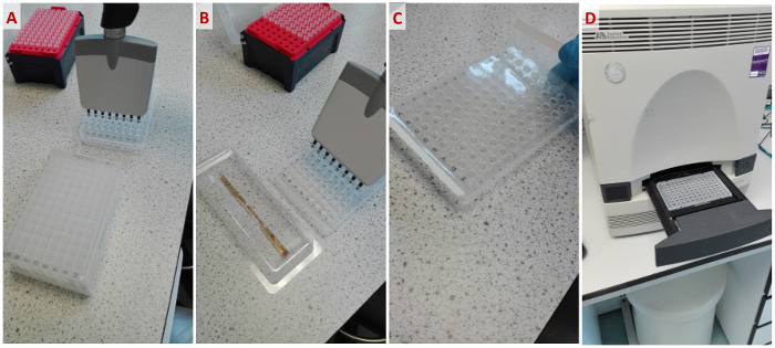
Figure 4: Workflow of a standard TSA experiment with the stability screens. From left to right: (A) Pipetting aliquots of the stability screens into a 96-well plate. (B) Pipetting protein sample with fluorescent dye into the plate. (C) Sealing the plate before centrifugation. (D) Placing the plate into an RT-PCR system. Please click here to view a larger version of this figure.
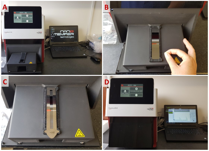
Figure 5: Workflow of a standard nanoDSF experiment. (A) Opening the capillary loading rack. (B) Loading the capillaries into the rack. (C) Immobilizing the capillaries with the magnetic sealing strip. (D) Programming an experiment. Please click here to view a larger version of this figure.
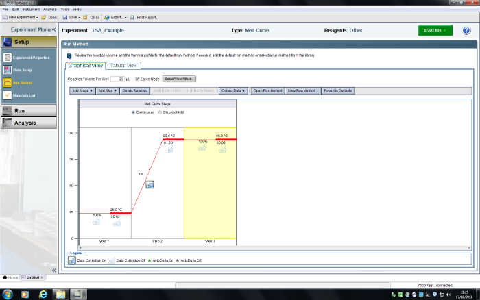
Figure 6: User interface for the RT-PCR system. A TSA experiment has been programmed. Please click here to view a larger version of this figure.
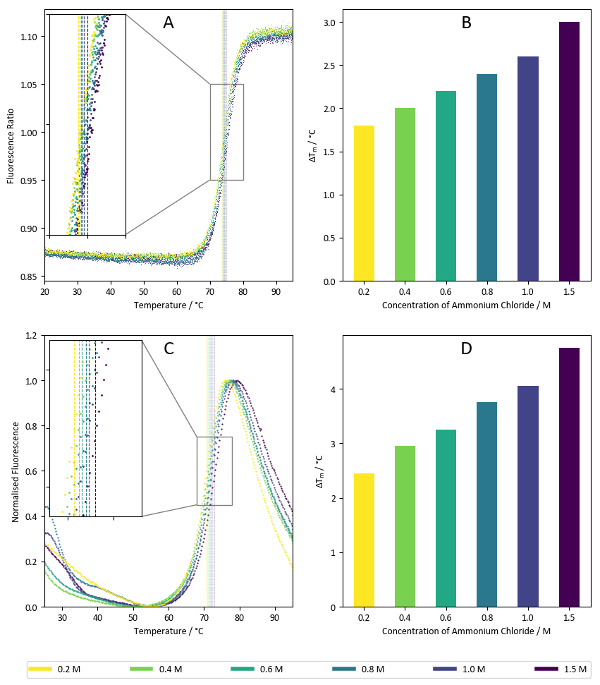
Figure 7: Salt screen sample data. (A) Ratio of fluorescence intensities at 350 nm vs 330 nm for a label-free nanoDSF experiment with lysozyme. Samples correspond to the wells C7-C12 of the salt screen (1.5 M – 0.2 M ammonium chloride). Calculated Tm values for each condition are superimposed on the plot. (B) Summary of Tm values calculated from the data presented in Figure 7A. (C) Fluorescence intensities at 590 nm for a TSA experiment using lysozyme with a hydrophobicity-sensitive reporter dye. Like Figure 7A, the samples correspond to the wells C7-C12 of the salt screen. Calculated Tm values are superimposed on the graph. (D) Summary of Tm values calculated from data present in Figure 7C. Please click here to view a larger version of this figure.
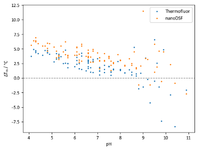
Figure 8: pH screen sample data. Summary of Tm shifts obtained with lysozyme and the pH screen. Each point represents an independent condition; points at the same pH value are of different buffer systems at the same pH. Tm shifts are calculated relative to a control Tm of 68.0 °C for TSA experiments and 71.9 °C for nanoDSF experiments. Please click here to view a larger version of this figure.
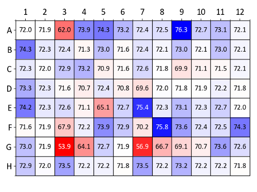
Figure 9: Osmolyte screen sample data (lysozyme). Summary of Tm values obtained from a label-free nanoDSF experiment with lysozyme and each well of the osmolyte screen. Tm values (in °C) are compared to the wells A1 and A2 which contain water as a control. A heatmap was generated based on ΔTm values compared (blue denotes a Tm increase and red a Tm decrease). Please click here to view a larger version of this figure.
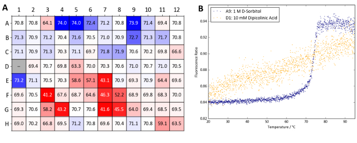
Figure 10: Osmolyte screen sample data (Protein X). (A) Summary of Tm values obtained from a label-free nanoDSF experiment with Protein X and the osmolyte screen. Tm values are compared to wells A1 and A2 which contain water as a control. A heatmap was generated based on ΔTm values compared (blue denotes a Tm increase and red a Tm decrease). (B) nanoDSF curves obtained from well A9 (1 M D-sorbitol, a stabilizing condition) and D1 (10 mM dipicolinic acid, a destabilizing condition). Please click here to view a larger version of this figure.
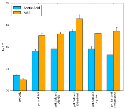
Figure 11: Buffer optimization effect on Tm. TSA Tm values of lysozyme combined with the conditions of each screen that afforded the largest increase in Tm. 100 mM acetic acid, pH 4.2, and 100 mM MES, pH 5.6, were chosen as the buffer systems, alongside 1.5 M ammonium sulphate as the salt. Osmolyte concentrations were identical to those found in the osmolyte screen: 10 mM Ala-Gly, 1 M D-sorbitol, 50 mM L-lysine and 100 mM hypotaurine. Error bars represent the standard deviation of six replicates. Please click here to view a larger version of this figure.
| Molecule | PDB Code | Frequency of Co-crystallisation |
| Phosphate | PO4 | 5132 |
| Acetate | ACT | 4521 |
| 2-(N-Morpholino)-Ethanesulfonic Acid (MES) | MES | 1334 |
| Tris(hydroxymethyl)aminomethane (tris) | TRS | 1155 |
| Formate | FMT | 1072 |
Table 1: Summary of buffer molecule co-crystallization frequency in Protein Data Bank (PDB) entries. Data obtained through PDBsum16 from a total of 144,868 entries (correct as of 12-5-18).
Supplementary Information. Please click here to download this file.
Supplementary Table 1. Please click here to download this file.
Supplementary Table 2. Please click here to download this file.
Supplementary Table 3. Please click here to download this file.
Discussion
Critical aspects within the protocol include the centrifugation step and proper sealing of the 96-well plate for TSA experiments (step 1.5). Centrifugation ensures that the protein sample and screen condition come into contact and mix. Additionally, if an unsealed plate is used for a TSA experiment, there is a significant risk of solvent evaporating throughout the experiment, causing an increase in sample concentration and increasing the chance of premature protein aggregation.
TSAs and nanoDSF are amenable to a wide range of protein samples; the vast majority of samples can produce interpretable melt curves with a hydrophobicity-based reporter dye or through dye-free nanoDSF. If standard fluorescence sources are not suitable for your protein, the simplest modification to the protocol that could be explored is the choice of fluorophore. Several alternative dyes could be suitable for TSA experiments. Examples include N-[4-(7-diethylamino-4-methyl-3-coumarinyl)phenyl]maleimide (CPM), a compound that fluoresces after reacting with a thiol27, and 4-(dicyanovinyl)julolidine (DCVJ), a compound that varies its fluorescence based on the rigidity of its environment, increasing its fluorescence as a protein sample unfolds28,29 (the latter dye often requires high concentrations of sample).
Alternative methods of melt curve analysis are available if Tm is not automatically calculated by the instrument software. If data is homogenous and only one denaturation step is apparent in the melt curves, a truncated dataset can be fitted to a Boltzmann sigmoid with the following equation:

Where F is the fluorescence intensity at temperature T, Fmin and Fmax are the fluorescence intensities before and after the denaturation transition, respectively, Tm is the midpoint temperature of the denaturation transition and C is the slope at Tm. While this method works well for simple two-step denaturation processes, it is unsuitable for complex melt curves with multiple transitions.
One of the major advantages of TSA is its accessibility; TSA experiments can be performed in any RT-PCR system with filters at suitable wavelengths for the fluorescence dye employed. This coupled with the low cost of consumables, ease of operation and relatively low amount of protein needed, make TSA a valuable technique for a wide range of project scales, both in industry and academia.
As well as indicating favorable buffer conditions, the screens contain some wells that may give clues to the presence of structural metals within a sample protein. Wells that may be of particular interest in the salt screen are G6 and G7, which contain 5 mM EDTA and 5 mM EGTA, respectively. Significant thermal destabilization in these wells may be indicative of important metal ions in the protein that are sequestered by the chelants. Compounds within the osmolyte screen can also potentially provide clues to the function of a protein. Many of the compounds in the screen belong to classes of molecule that are common substrates of enzymes. For example, the general stabilization afforded by saccharides (present in wells A11-B10) for lysozyme could be attributed to their structural similarity to established substrates of the enzyme, N-acetylglucosamine oligomers30.
The TSA and nanoDSF protocols outlined above can also be adapted to study protein-ligand interactions. Ligands that bind specifically to a protein can increase its thermal stability by introducing new interactions within the complex. A dose-dependent positive shift in protein Tm is a promising sign of a successful protein-ligand interaction. The speed, throughput and low cost of screening compound libraries with TSAs has made it a very popular method in early-stage drug discovery.
Optimizing the buffer conditions of target proteins and their ligand complexes can be essential for a project's success, as many literature examples demonstrate31,32,33,34. With a typical assay taking under 2 h including setup time, TSAs and nanoDSF coupled with stability screens represent a fast, inexpensive technique for buffer optimizations.
Disclosures
The authors have nothing to disclose.
Acknowledgements
This project has received funding from the European Research Council (ERC) under the European Union’s Horizon 2020 research and innovation programme (grant agreement n° 685778). This work was supported by the Biotechnology and Biological Sciences Research Council (BBSRC, grant numbers BB/M011186/1, BB/J014516/1). DB thanks the BBSRC Doctoral Training Partnership Newcastle-Liverpool-Durham for a studentship and Durham University Department of Biosciences for contributing toward the funding this work. We thank Ian Edwards for his help and the Durham University Department of Chemistry Mass Spectrometry department for their instrumental analysis of Protein X. We are grateful to Arnthor Ævarsson for his work with the Virus-X project, and thanks also to Claire Hatty and NanoTemper GmbH for lending and assisting with the Prometheus NT.48 system for this project. Finally, thank you to Frances Gawthrop and Tozer Seeds for their support as part of the BBSRC iCASE award.
Materials
| Lysozyme | Melford Laboratories | L38100 | Crystallised and lyophilised chicken egg white lysozyme. |
| The Durham pH Screen | Molecular Dimensions | MD1-101 | 96-well protein stability screen. See above for contents. |
| The Durham Salt Screen | Molecular Dimensions | MD1-102 | 96-well protein stability screen. See above for contents. |
| The Durham Osmolyte Screen | Various | #N/A | 96-well protein stability screen, not commercially available at the time of publication. See above for contents. |
| SYPRO Orange | Invitrogen | S6651 | Widely used fluorescent dye for protein staining in gels and DSF. |
| 96-well PCR Plate | Starlab | 1403-7700 | Semi-skirted clear plastic for use with AB 7500 Fast RT-PCR System. |
| 7500 Fast Real-time PCR System | Applied Biosystems | 4362143 | 96-well format RT-PCR system. Alternative systems can be used. Analysis of data performed using free, open-access software NAMI. AB software tailored to DSF experiments using the 7500 Fast available at additional cost. |
| Prometheus NT.48 | NanoTemper Technologies | #N/A | Label-free DSF system with up to 48-sample capacity. Can calculate unfolding temperatures (Tm and Tonset), critical denaturant concentrations (Cm), free folding energy (ΔG and ΔΔG), and aggregation results (Tagg) using built-in software. |
| Prometheus NT.48 Series nanoDSF Grade Standard Capillaries | NanoTemper Technologies | PR-C002 | Prometheus NT.48 Series nanoDSF Grade Standard Capillaries. "High sensitivity" variants are available at a higher cost for use with low-concentration samples (<200 µg ml-1). |
References
- Kapust, R. B., Waugh, D. S. Controlled intracellular processing of fusion proteins by TEV protease. Protein Expression and Purification. 19 (2), 312-318 (2000).
- Cordingley, M. G., Register, R. B., Callahan, P. L., Garsky, V. M., Colonno, R. J. Cleavage of small peptides in vitro by human rhinovirus 14 3C protease expressed in Escherichia coli. Journal of Virology. 63 (12), 5037-5045 (1989).
- Hjorleifsdottir, S., Aevarsson, A., Hreggvidsson, G. O., Fridjonsson, O. H., Kristjansson, J. K. Isolation, growth and genome of the Rhodothermus RM378 thermophilic bacteriophage. Extremophiles. 18 (2), 261-270 (2014).
- Alva, V., Nam, S. Z., Söding, J., Lupas, A. N. The MPI bioinformatics Toolkit as an integrative platform for advanced protein sequence and structure analysis. Nucleic Acids Research. 44, 410-415 (2016).
- McPherson, A. Protein Crystallization. Methods in molecular biology. 1607, 17-50 (2017).
- Ericsson, U. B., Hallberg, B. M., DeTitta, G. T., Dekker, N., Nordlund, P. Thermofluor-based high-throughput stability optimization of proteins for structural studies. Analytical Biochemistry. 357 (2), 289-298 (2006).
- Reinhard, L., Mayerhofer, H., Geerlof, A., Mueller-Dieckmann, J., Weiss, M. S. IUCr Optimization of protein buffer cocktails using Thermofluor. Acta Crystallographica Section F Structural Biology and Crystallization Communications. 69 (2), 209-214 (2013).
- Boivin, S., Kozak, S., Meijers, R. Optimization of protein purification and characterization using Thermofluor screens. Protein Expression and Purification. 91 (2), 192-206 (2013).
- Kozak, S., Lercher, L., Karanth, M. N., Meijers, R., Carlomagno, T., Boivin, S. Optimization of protein samples for NMR using thermal shift assays. Journal of Biomolecular NMR. 64 (4), 281-289 (2016).
- Semisotnov, G. V., Rodionova, N. A., Razgulyaev, O. I., Uversky, V. N., Gripas’, A. F., Gilmanshin, R. I. Study of the “molten globule” intermediate state in protein folding by a hydrophobic fluorescent probe. Biopolymers. 31 (1), 119-128 (1991).
- Grøftehauge, M. K., Hajizadeh, N. R., Swann, M. J., Pohl, E. Protein-ligand interactions investigated by thermal shift assays (TSA) and dual polarization interferometry (DPI). Acta Crystallographica Section D: Biological Crystallography. 71, 36-44 (2015).
- Steinberg, T. H., Jones, L. J., Haugland, R. P., Singer, V. L. SYPRO Orange and SYPRO Red Protein Gel Stains: One-Step Fluorescent Staining of Denaturing Gels for Detection of Nanogram Levels of Protein. Analytical biochemistry. 239, 223-237 (1996).
- Burstein, E. A., Vedenkina, N. S., Ivkova, M. N. Fluorescence and the location of tryptophan residues in protein molecules. Photochemistry and Photobiology. 18 (4), 263-279 (1973).
- Haffke, M., Rummel, G., Boivineau, J., Münch, A., Jaakola, V. -. P. nanoDSF: label-free thermal unfolding assay of G-protein-coupled receptors for compound screening and buffer composition optimization. Application Note NT-PR-008. , (2016).
- Chari, A., et al. ProteoPlex: stability optimization of macromolecular complexes by sparsematrix screening of chemical space. Nature Methods. 12 (9), 859-865 (2015).
- Laskowski, R. A. PDBsum: summaries and analyses of PDB structures. Nucleic Acids Research. 29 (1), 221-222 (2001).
- Good, N. E., Winget, G. D., Winter, W., Connolly, T. N., Izawa, S., Singh, R. M. Hydrogen ion buffers for biological research. Biochemistry. 5 (2), 467-477 (1966).
- Good, N. E., Izawa, S. Hydrogen ion buffers. Methods in enzymology. 24, 53-68 (1972).
- Ferguson, W. J., et al. Hydrogen ion buffers for biological research. Analytical biochemistry. 104 (2), 300-310 (1980).
- Welch, W. J., Brown, C. R. Influence of molecular and chemical chaperones on protein folding. Cell stress & chaperones. 1 (2), 109-115 (1996).
- Diamant, S., Eliahu, N., Rosenthal, D., Goloubinoff, P. Chemical chaperones regulate molecular chaperones in vitro and in cells under combined salt and heat stresses. The Journal of biological chemistry. 276 (43), 39586-39591 (2001).
- Yancey, P. H. Organic osmolytes as compatible, metabolic and counteracting cytoprotectants in high osmolarity and other stresses. Journal of Experimental Biology. 208 (15), 2819-2830 (2005).
- Garman, E. F., Owen, R. L. Cryocooling and radiation damage in macromolecular crystallography. Acta Crystallographica Section D Biological Crystallography. 62 (1), 32-47 (2006).
- de Marco, A., Vigh, L., Diamant, S., Goloubinoff, P. Native folding of aggregation-prone recombinant proteins in Escherichia coli by osmolytes, plasmid- or benzyl alcohol- overexpressed molecular chaperones. Cell Stress & Chaperones. 10 (4), 329 (2005).
- Berman, H. M., et al. The protein data bank. Nucleic acids research. 28 (1), 235-242 (2000).
- Bougouffa, S., Radovanovic, A., Essack, M., Bajic, V. B. DEOP: A database on osmoprotectants and associated pathways. Database. 2014, 1-13 (2014).
- Alexandrov, A. I., Mileni, M., Chien, E. Y. T., Hanson, M. A., Stevens, R. C. Microscale Fluorescent Thermal Stability Assay for Membrane Proteins. Structure. 16 (3), 351-359 (2008).
- Kung, C. E., Reed, J. K. Fluorescent molecular rotors: a new class of probes for tubulin structure and assembly. Biochemistry. 28 (16), 6678 (1989).
- Iio, T., Itakura, M., Takahashi, S., Sawada, S. 9-(Dicyanovinyl)julolidine binding to bovine brain calmodulin. Journal of biochemistry. 109 (4), 499-502 (1991).
- Veros, C. T., Oldham, N. J. Quantitative determination of lysozyme-ligand binding in the solution and gas phases by electrospray ionisation mass spectrometry. Rapid Communications in Mass Spectrometry. 21 (21), 3505-3510 (2007).
- Kean, J., Cleverley, R. M., O’Ryan, L., Ford, R. C., Prince, S. M., Derrick, J. P. Characterization of a CorA Mg2+ transport channel from Methanococcus jannaschii using a Thermofluor-based stability assay. Molecular membrane biology. 25 (8), 653-661 (2008).
- Geders, T. W., Gustafson, K., Finzel, B. C. Use of differential scanning fluorimetry to optimize the purification and crystallization of PLP-dependent enzymes. Acta Crystallographica Section F. 68 (5), 596-600 (2012).
- Morgan, H. P., Zhong, W., McNae, I. W., Michels, P. A., Fothergill-Gilmore, L. A., Walkinshaw, M. D. Structures of pyruvate kinases display evolutionarily divergent allosteric strategies. Royal Society open science. 1 (140120), (2014).
- Moretti, A., Li, J., Donini, S., Sobol, R. W., Rizzi, M., Garavaglia, S. Crystal structure of human aldehyde dehydrogenase 1A3 complexed with NAD+ and retinoic acid. Scientific reports. 6 (35710), (2016).

