Implementation of Interference Reflection Microscopy for Label-free, High-speed Imaging of Microtubules
Summary
This protocol is a guide for implementing interference reflection microscopy on a standard fluorescence microscope for label-free, high-contrast, high-speed imaging of microtubules using in vitro surfaces assays.
Abstract
There are several methods for visualizing purified biomolecules near surfaces. Total-internal reflection fluorescence (TIRF) microscopy is a commonly used method, but has the drawback that it requires fluorescent labeling, which can interfere with the activity of the molecules. Also, photobleaching and photodamage are concerns. In the case of microtubules, we have found that images of similar quality to TIRF can be obtained using interference reflection microscopy (IRM). This suggests that IRM might be a general technique for visualizing the dynamics of large biomolecules and oligomers in vitro. In this paper, we show how a fluorescence microscope can be modified simply to obtain IRM images. IRM is easier and considerably cheaper to implement than other contrast techniques such as differential interference contrast microcopy or interferometric scattering microscopy. It is also less susceptible to surface defects and solution impurities than darkfield microscopy. Using IRM, together with the image analysis software described in this paper, the field of view and the frame rate is limited only by the camera; with a sCMOS camera and wide-field illumination microtubule length can be measured with precision up to 20 nm with a bandwidth of 10 Hz.
Introduction
Label-free imaging of microtubules is of interest as it circumvents the need for fluorescent labeling of tubulin to generate contrast in the images. Fluorescent labeling has several drawbacks: it not feasible if the protein concentration is low1 and photobleaching and photodamage limit the observation time. Several techniques have been used to image label-free microtubules, including video-enhanced differential interference contrast microscopy (DIC) and darkfield microscopy2,3,4,5. Recently, interferometric scattering microscopy (iSCAT)6, rotating-coherent-scattering microscopy (ROCS)7 and spatial light interference microscopy (SLIM)8, have also been used. All these techniques are capable of imaging microtubules and have proved to be valuable for studying microtubule dynamics. However, each have their own limitations. In DIC the contrast depends on the angle between the microtubule and the Nomarski prism axis. In darkfield, the microtubule signal is degraded by scattered light from impurities or surfaces defects. Though iSCAT exhibits extraordinary sensitivity (down to single proteins) and ROCS can image microtubules deeper into the sample, both methods are technically demanding, requiring laser scanners.
This protocol demonstrates how interference reflection microscopy (IRM)9, 10 can be set up as an alternative technique for label-free imaging of microtubules. IRM is easy to implement as it requires only the addition of an inexpensive 50/50 mirror to a standard fluorescent microscope. When used in conjunction with the software described here, IRM produces high contrast microtubule images, can image large fields of view at high speed, requires a onetime alignment, and can easily be combined with other techniques such as fluorescence imaging.
Protocol
1. Microscope modification and objective lens
- Insert a 50/50 mirror into the filter wheel of the fluorescent microscope using an appropriate filter cube (Figure 1). Handle the 50/50 mirror with care as often they have anti-reflection coating.
NOTE: We used a 50/50 mirror in an empty filter cube of the microscope. The 50/50 mirror is inserted where the dichroic mirror is located. - Use a high magnification/high NA oil objective.
NOTE: In this protocol, we used a 100x/1.3 NA objective.
2. Chamber preparation to adhere microtubules to the surface
- Clean microscope slides and 22 mm x 22 mm coverslips (for upright microscope) or 22 mm x 22 mm and 18 mm x 18 mm coverslips (for inverted microscopes). Modify the surface as needed. For example, clean the coverslips using an alkaline detergent (see Table of Materials) followed by 100% ethanol with distilled water washes in between and after11.
- Cut 3 mm wide strips of plastic paraffin film (see Table of Materials) using a razor blade and another microscope slide as an edge.
- Place two plastic paraffin film strips 3 mm apart on a clean 22 x 22mm cover slip. Then place an 18 mm x 18 mm coverslip to form a channel. If using an upright microscope, place the strips on top of a clean microscope slide and then place a coverslip on top.
- Place the coverslip (or slide) on a heat block at 100 °C for 10-30 s for the paraffin film to form a sealed channel.
- Flow in 50 µg/mL of antibody (in Brinkley Buffer 1980 (BRB80)) by perfusion using a pipette. Incubate for 10 min.
NOTE: We use anti-rhodamine antibodies to bind rhodamine-labeled microtubule seeds to the surface. Alternatively, avidin can be used to bind biotin-labelled microtubule seeds or to biotinylated gold particles. To simply look at microtubules in the absence of tubulin in solution (i.e., a non-dynamic assay), an anti-tubulin antibody can be used. - Wash five times with BRB80 buffer. It is recommended to filter the solutions using a 0.22 µm filter.
- Flow in 1% poloxamer 407 (a triblock copolymer) in BRB80 to block the surface against non-specific binding. Incubate for 10 min.
- Wash five times with BRB80 buffer.
- The sample is ready to be placed on the microscope. To prevent the sample from drying out, add two droplets of BRB80 buffer at the ends of the channel and replenish when needed.
3. Microscope alignment
- Place the sample on the microscope stage. Turn on the epi-illumination light source.
- Focus on the sample surface. You will observe multiple surfaces as the objective is moved up and down due to back reflection of light from optics within the optical path. A good method to find the sample surface is to focus on the paraffin film edge. Once the surface is found, set the field of view to the center of the chamber.
- Center the field diaphragm in the field of view by closing it half way and using the adjustment screws. Once aligned, reopen the diaphragm.
NOTE: Screw adjustment only needs to be done sporadically, perhaps every 3-6 months or when troubleshooting. - Slide in the Bertrand lens to view the exit pupil (back focal plane) of the objective.
- Close the aperture diaphragm (AD) beyond the edges of the exit pupil of the objective.
- Use the adjustment screws to center the AD with the exit pupil. Double check by opening the AD and matching its edges with those of the exit pupil.
NOTE: This adjustment only needs to be done sporadically. - Set the aperture diaphragm to about 2/3 of the NA of the objective. See section 7 for detailed procedures for optimizing the aperture diaphragm.
4. Imaging stabilized microtubules or 40 nm gold particle
NOTE: Stabilized microtubules and gold nanoparticles serve as good control samples. It is recommended to image surface attached microtubules or gold nanoparticles as a first step to assess IRM performance and help in setting the optimal aperture diaphragm opening (section 7).
- Set the exposure time of the camera to 10 ms and adjust the illumination to nearly saturate the camera dynamic range.
- Flow in 10 µL of guanylyl-(alpha, beta)-methylene-diphosphonate (GMPCCP)- or taxol-stabilized microtubules in BRB804,12,13 (or 40 nm gold particles) by perfusion using a pipette to a fresh sample and monitor binding by imaging the surface. Once 10-20 microtubules are bound within the field of view, wash the sample 2x with BRB80.
NOTE: With a well aligned microscope, the microtubules should be visible without background subtraction. - Acquire 10 images by setting a time lapse with 1 second delay period for 10 seconds (at 10 ms exposure).
- Acquire a background image. To do so, move the stage using the stage controller or computer software along the channel long axis while acquiring 100 images with no delay (i.e. streaming close to 100 fps @ 10 ms exposure).
NOTE: The background is the median of the 100 images. By taking the median, the illumination profile and other stationary features like dirt on the optics are preserved while everything else is filtered out. There should be no tilt on the sample as this will lead to change in the axial position as the stage is moved and ultimately degrade the background image. If the tilt cannot be avoided, then an alternative method is to acquire averaged background images before flowing the seeds. - For processing and analyzing the images, go to step 6.
5. Imaging microtubule dynamics
- For microtubule dynamics using brain tubulin, set the sample heater temperature to 37 °C.
- Flow in 10 µL of GMPCCP-stabilized microtubule seeds in BRB8011 by perfusion using a pipette to a fresh sample and monitor them binding to the surface by imaging the surface live (i.e., while streaming). Once 10-20 seeds are bound with field of view, wash the sample using 2x channel volume with BRB80 (BRB80 should be prewarmed to 37 °C or at least at room temperature).
NOTE: With a well aligned microscope, the seeds should be visible without background subtraction. - Flow in the polymerization mix (7.5 µM unlabeled tubulin + 1 mM guanosine triphosphate (GTP) + 1 mM Dithiothreitol (DTT) in BRB80 buffer). For measuring microtubule growth, set a time-lapse using the acquisition software to acquire an image every 5 seconds (0.2 frames per second (fps)) for 15 minutes.
- To enhance the contrast, acquire 10 images (instead of one) at each time point and average them. For microtubule shrinkage, acquire images at 100 fps by setting the time delay to 0 and an exposure time of 10ms (higher fps is possible with smaller regions of interest depending on the camera used).
- Acquire a background image as in step 4.4.
6. Image processing and analysis
NOTE: For analysis, this protocol uses Fiji14 but the reader is free to use any software she/he find suitable.
- Open saved background images.
- Calculate the median image (i.e. background) using Image > Stack > Z project > Median.
- Open microtubule dynamics movie as a stack (same for non-dynamic microtubules) using File > Open.
- Subtract the background image from the stack using Process > Image calculator. Make sure to check the “32bit (float) result” option.
- For dynamic microtubules, using the line tool draw a line along the microtubule of interest and add it to the region of interest manager by pressing “t”. Repeat for all microtubules of interest.
- For dynamic microtubules, run the Multi-Kymo macro (Supplementary File 1). The macro will generate a video and a kymograph for every microtubule in the ROI manager. Every microtubule will get a unique identifier.
- For dynamic microtubules, run the Kymo-Analysis macro (Supplementary File 2) and follow its steps to measure the growth rates and shrinkage rates of the microtubules.
7. Aperture diaphragm size
NOTE: An important factor for acquiring high contrast images of microtubules using IRM is setting the illumination numerical aperture (INA) correctly10,15. The INA can be changed by changing the size of the incoming illumination beam at the objective’s exit pupil which is controlled by the size of the AD (the AD is located at a conjugate plane with the exit pupil (back focal plane) of the objective, Figure 1):

where DAD is the diameter of the aperture diaphragm, fobjective is the focal length of the objective and Dep is the objective’s exit pupil diameter. Typically, the AD is left fully open for fluorescence imaging, so the INA equals the objective’s NA. In a fluorescence microscope, the AD scale does not indicate its diameter, thus the INA can’t be calculated. It’s possible to calibrate the AD size with the help of an objective. Yet, it’s not necessary since the AD size would be fixed to the size that produces the highest contrast.
- Prepare a sample of fluorescently labelled stabilized microtubules stuck to the surface (steps 4.1-4.2).
NOTE: We used tetramethylrhodamine labeled microtubules16 (Ex: 550 nm, Em: 580 nm). - Bring microtubules into focus using the microscope focusing knob while fluorescently imaging them (if microtubules are not labelled, image them with IRM15 or DIC5).
- Set camera exposure to 10 ms using the camera software.
NOTE: This exposure is arbitrary and an exposure of 100 ms would also work. - Close down the AD to its smallest opening. Adjust the illumination to nearly saturate the camera’s dynamic range or to the maximum possible.
NOTE: As a guide, use the look up table typically provided by the acquisition software. - Acquire 10 images (by streaming or taking an image every second) of a field of view containing 10+ microtubules.
- Acquire a background image as in step 4.4.
- Change the size of the AD and repeat steps 7.5-7.6 for the whole AD opening range (from closed to the exit pupil size, Figure 2). Every time the AD size is changed, adjust the illumination intensity to match that of step 7.4.
- For every field of view acquired, subtract the corresponding background using process > image calculator and choosing “subtract” from the drop-down menu. Make sure the “32bit (float) result” option is checked. Then average the resulting images using image > stack > Z project > average.
- Measure the signal-to-background noise ratio (SBR) of the microtubules defined as the average intensity of the microtubule signal (intensity of the microtubule minus the intensity of the background) divided by the standard deviation of the background (Figure 3).
- Determine the optimal AD size (i.e. optimal INA) by calculating the average SBR of the microtubules for every opening size and set the AD size to the one producing the highest SBR (Figure 2). It is possible that there is a range of AD sizes that produce comparable contrast15.
Representative Results
As mentioned above, with a well aligned microscope, microtubules should be visible without background subtraction (Figure 4A). Subtracting the background (Figure 4B) enhances the contrast of microtubule (Figure 4C). To further enhance the contrast, averaging or Fourier filtering or a combination of both can be used (Figure 4D,F,E). The line scans in Figure 4G shows the incremental improvement of image quality. Notice the reduction of background noise with each processing step.
Examples of kymographs of microtubule dynamics generated from time-lapse movies are shown in Figure 5. The videos were acquired at two frame rates: 0.2 fps (slow) and 100 fps (fast). The former is suitable for measuring growth rates while the latter is more suitable for measuring shrinkage rate that is an order of magnitude faster than the growth rate.
For the case where gold nanoparticles are used for setting up the microscope, an example image is shown in Figure 6. Gold nanoparticles were passively attached to the surface. While 40 nm particles are recommended, it is also possible to image 20 nm particles, yet at a lower contrast.
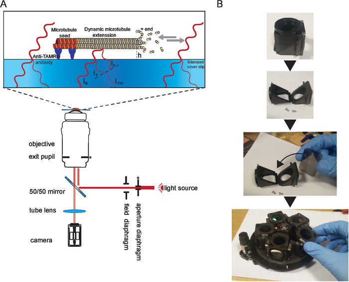
Figure 1. Schematic representation of IRM. (A) Epi-illumination from the light source passes through the aperture diaphragm before reaching the 50/50 mirror. The aperture diaphragm sets the beam width thus the illumination NA. The 50/50 mirror partially reflects the light up to the objective to illuminate the sample. Light reflected from the sample is collected and then projected onto the camera chip (by the tube lens) where it interferes to generate the image. Image contrast is the result of the interference between the light reflected from the glass/water interface (I1) and the light reflected from the water/microtubule interface (I2). Depending on the microtubule/surface distance (h), the optical path difference between I1 and I2 will result in a constructive (bright signal) or destructive (dark signal) or anything in between. For example, if light with a wavelength of 600 nm is used for imaging, the contrast will switch between dark and bright when the microtubule height changes by about 100 nm. The asterisk indicate conjugate planes (modified from15). (B) Example of the 50/50 mirror installation. A suitable filter cube was opened and the mirror was inserted where a dichroic mirror usually sits. The mirror was oriented as per manufacturer instructions. Then the cube was inserted in the filter wheel which was inserted back to the microscope (not shown). During the installation, gloves were used, and the mirror was only held by the edges. Please click here to view a larger version of this figure.
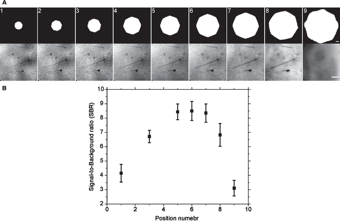
Figure 2. Optimal Aperture diaphragm setting. (A) Same field of view was imaged at different aperture diaphragm openings without background subtraction. Visually, the contrast increased as the size of the aperture diaphragm increased till it reached a plateau and started to degrade afterwards. This was confirmed by (B) SBR measurements of background subtracted images. Error bars are standard deviation. Scale bars are 500 µm (AD) and 3 µm (microtubules). Please click here to view a larger version of this figure.
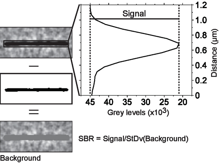
Figure 3. Measuring signal-to-background noise ratio. Microtubules were isolated in regions of interest. Each region of interest was thresholded to separate the microtubule from the background. The average microtubule signal was obtained from a line scan across the microtubule. The scan line width was set to equal the microtubule length. This way, every point on the scan is an average of the signals of all pixels along the microtubule axis that are parallel to that point. The background noise is the standard deviation of all the pixels below threshold cut off. Please click here to view a larger version of this figure.
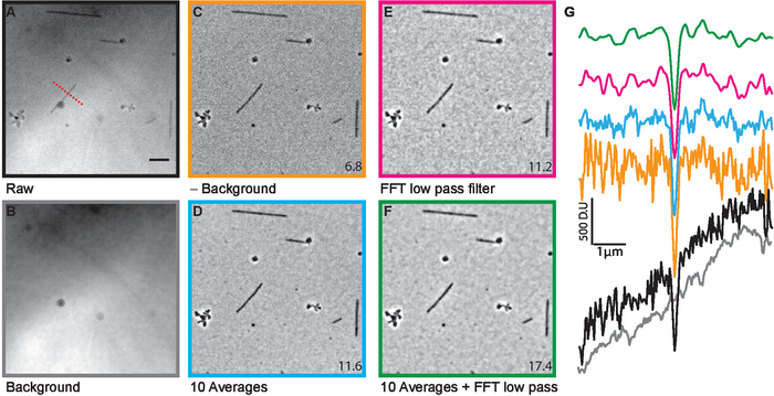
Figure 4. Image processing. After acquiring raw images (A), the background (B) was subtracted (C) to enhance the microtubule contrast. To further improve the contrast the images were either averaged (D) or Fourier filtered (E) or both (F). The line scans (G), whose location is indicated by the dashed red line in (A) are color matched to the various images in (A) à (F). The numbers at the lower corner are average SBRs measured for the whole field of view. The scale bar is 5 µm (modified from15) . Please click here to view a larger version of this figure.
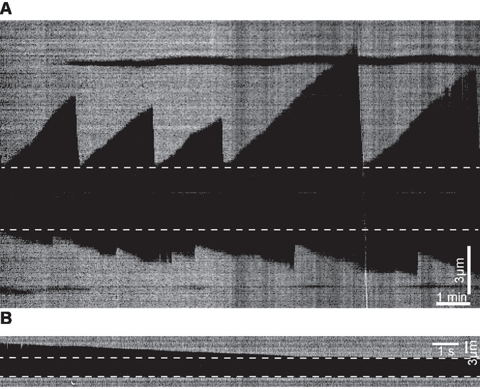
Figure 5. Examples of kymographs. (A) Kymograph examples of microtubule dynamics generated from time-lapse movies acquired at 0.2 fps. (B) Kymograph depicting an example of a shrinkage event generated from a movie acquired at 100 fps. Dashed lines mark the seeds. Please click here to view a larger version of this figure.
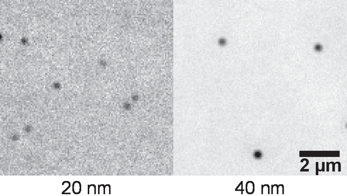
Figure 6. Example of gold nanoparticles imaged with IRM. Gold nanoparticles of sizes 20 and 40 nm were passively attached to the surface. 10 images were acquired. After background subtraction, the images were averaged to enhance contrast. Please click here to view a larger version of this figure.
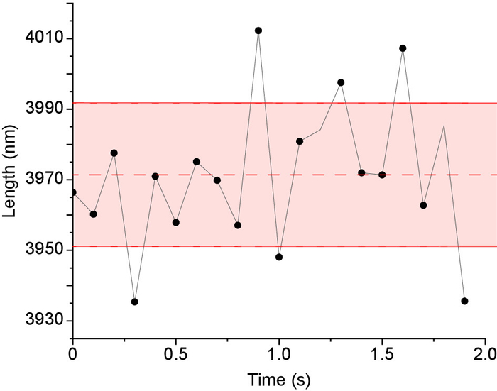
Figure 7. Microtubule length Tracking precision in IRM images. Stabilized microtubules (i.e., fixed lengths) were imaged 200x at 100 fps then averaged to 10 fps to enhance contrast. Next, the microtubules’ lengths were measured using Fiesta17 tracking software. For every microtubule the mean length and standard deviation were calculated as shown in the figure (dashed line represents the mean and solid red lines represents the standard deviation, length = 3971 ± 20 nm. The overall tracking precision was the average of the standard deviation of all tracked microtubules (n = 6 microtubules x 20 data points = 120 data points). Please click here to view a larger version of this figure.
Supplementary File 1. Please click here to download this file.
Supplementary File 2. Please click here to download this file.
Discussion
This protocol demonstrated the successful use of IRM for imaging and measurement of the microtubule dynamics. Care should be given to correctly set the illumination numerical aperture as it has the strongest impact on image contrast. Also, using high numerical aperture (NA) objectives is important for getting high resolution/high contrast images, as higher NA objective have higher light collecting power compared to low NA objectives. The cleaner the surface and solutions used the lower the noise as dirt ends up attaching to the surface and adding (over the course of the experiment) speckle like noise to the images. Acquisition of a background image is important as well as it removes illumination inhomogeneities, static noise and surface irregularities.
A recommended modification is to introduce a long pass filter (>600 nm) in the illumination path. The spectrum of white light sources typically contains wavelengths in the UV which can damage microtubules. In addition, using long wave length for IRM comes in handy when combining IRM with fluorescence (e.g., when studying the effect of microtubule associated proteins (MAPs) on microtubule dynamics). Be aware that when imaging for expended period of times, sample drift (especially along the optical axis) decreases image contrast due to the deviation of the image plane from the background plane. Modern microscopes are often equipped with stabilization mechanisms (e.g., perfect focus (Nikon), Definite focus.2 (Zeiss), IX3-ZDC2 (Olympus)). An alternative solution is to thermally stabilize the setup either passively or actively18 or by correcting for drift19,20,21. Finally, microtubule contrast can be increased by reducing the size of field diaphragm (a 70% opening is good choice as it is a balance between increasing contrast and field of view size)15.
While IRM is suitable for imaging microtubules it is not sensitive enough to detect single proteins. For such application, iSCAT is a more suitable technique. Similarly, fluorescence and iSCAT are better suited if tracking precision of less than 10 nm is needed. For IRM, the measured length tracking precision is ~20 nm as shown in Figure 7.
Use of IRM in surface assays can go beyond microtubules; for example, molecular motors can be labelled with gold nanoparticles and tracked as they interact with microtubules. In addition a more advanced form of IRM known as reflective interference contrast microscopy (RICM)22 can, in principle, be used to further enhance microtubules contrast and obtain higher tracking precision.
Divulgations
The authors have nothing to disclose.
Acknowledgements
The Authors thank Anna Luchniak and Yin-wei Kuo for critical reading and comments on the protocol.
Materials
| Microscope | Nikon | Ti-Eclipse | An inverted microscope used for perfoming the expriments |
| 50/50 beam splitter | Chroma | 21000 | When buying make sure to choose the splitter dimensions that fit the cube used in the microscope |
| NIKON PLAN FLUOR 100X/0.5-1.3 Iris objective | Nikon | MRH02902 | Imaging objective. This objective has a NA adjusting iris that was opened to NA 1.3 |
| Mucasol universal detergent | Sigma-aAldrich | Z637181-2L | Used for cleaning coverslips and slides |
| plastic paraffin film (commerical name Parafilm M) | Sigma-aAldrich | P7793 | Used for constructing flow channels |
| Anti-TAMRA antibody | Invitrogen | A-6397 | Used to bind TAMRA labeled molecules (e.g. microtubules) to the sample surface. RRID (AB_2536196) |
| Poloxamer 407 (commercial name Pluronic F-127) | Sigma-aAldrich | Used for blocking the channel surface to prevent nonspecific binding | |
| 40 nm gold nanoparticles | Sigma-aAldrich | 753637 | Used as a control sample |
| 20 nm gold nanoparticles | Sigma-aAldrich | 753610 | Used as a control sample |
| Zyla 4.2 Camera | Andor | Zyla 4.2 | 2048×2048 pixles (6.5µm pixel size) with quantum efficiency of 72% and 16bit dynamic range |
| Feista tracking software | https://www.bcube-dresden.de/fiesta/wiki/FIESTA | ||
| Stabilized microtubles | prepared in house (see references in text) |
References
- Widlund, P. O., et al. One-step purification of assembly-competent tubulin from diverse eukaryotic sources. Molecular Biology of the Cell. 23 (22), 4393-4401 (2012).
- Walker, R. A., et al. Dynamic instability of individual microtubules analyzed by video light microscopy: rate constants and transition frequencies. The Journal of Cell Biology. 107 (4), 1437-1448 (1988).
- Hotani, H., Horio, T. Dynamics of microtubules visualized by darkfield microscopy: Treadmilling and dynamic instability. Cell Motility and the Cytoskeleton. 10 (1-2), 229-236 (1988).
- Gittes, F., Mickey, B., Nettleton, J., Howard, J. Flexural rigidity of microtubules and actin filaments measured from thermal fluctuations in shape. The Journal of Cell Biology. 120 (4), 923-934 (1993).
- Bormuth, V., Howard, J., Schäffer, E. LED illumination for video-enhanced DIC imaging of single microtubules. J Microsc. 226 (Pt 1), 1-5 (2007).
- Andrecka, J., Ortega Arroyo, J., Lewis, K., Cross, R. A., Kukura, P. Label-free Imaging of Microtubules with Sub-nm Precision Using Interferometric Scattering Microscopy. Biophysical Journal. 110 (1), 214-217 (2016).
- Koch, M. D., Rohrbach, A. Label-free Imaging and Bending Analysis of Microtubules by ROCS Microscopy and Optical Trapping. Biophysical Journal. 114 (1), 168-177 (2018).
- Kandel, M. E., Teng, K. W., Selvin, P. R., Popescu, G. Label-Free Imaging of Single Microtubule Dynamics Using Spatial Light Interference Microscopy. ACS Nano. 11 (1), 647-655 (2017).
- Curtis, A. S. G. The Mechanism of Adhesion of Cells to Glass. The Journal of Cell Biology. 20 (2), 199-215 (1964).
- Weber, I. [2] Reflection interference contrast microscopy. Methods in Enzymology. 361, 34-47 (2003).
- Gell, C., et al. Chapter 13 – Microtubule Dynamics Reconstituted In Vitro and Imaged by Single-Molecule Fluorescence Microscopy. Methods in Cell Biology. 95, 221-245 (2010).
- Nitzsche, B., et al. Chapter 14 – Studying Kinesin Motors by Optical 3D-Nanometry in Gliding Motility Assays. Methods in Cell Biology. 95, 247-271 (2010).
- Schiff, P. B., Fant, J., Horwitz, S. B. Promotion of microtubule assembly in vitro by taxol. Nature. 277 (5698), 665-667 (1979).
- Schindelin, J., et al. Fiji: an open-source platform for biological-image analysis. Nature Methods. 9 (7), 676-682 (2012).
- Mahamdeh, M., Simmert, S., Luchniak, A., Schäffer, E., Howard, J. Label-free high-speed wide-field imaging of single microtubules using interference reflection microscopy. Journal of Microscopy. 272 (1), 60-66 (2018).
- Hyman, A., et al. [39] Preparation of modified tubulins. Methods in Enzymology. 196, 478-485 (1991).
- Ruhnow, F., Zwicker, D., Diez, S. Tracking Single Particles and Elongated Filaments with Nanometer Precision. Biophysical Journal. 100 (11), 2820-2828 (2011).
- Mahamdeh, M., Schäffer, E. Optical tweezers with millikelvin precision of temperature-controlled objectives and base-pair resolution. Optics Express. 17 (19), 17190-17199 (2009).
- Kim, K., Saleh, O. A. Stabilizing method for reflection interference contrast microscopy. Applied Optics. 47 (12), 2070-2075 (2008).
- Ortega Arroyo, J., Cole, D., Kukura, P. Interferometric scattering microscopy and its combination with single-molecule fluorescence imaging. Nature Protocols. 11 (4), 617-633 (2016).
- Carter, A. R., King, G. M., Ulrich, T. A., Halsey, W., Alchenberger, D., Perkins, T. T. Stabilization of an optical microscope to 0.1 nm in three dimensions. Appl Opt. 46 (3), 421-427 (2007).
- Limozin, L., Sengupta, K. Quantitative Reflection Interference Contrast Microscopy (RICM) in Soft Matter and Cell Adhesion. ChemPhysChem. 10 (16), 2752-2768 (2009).

