X-ray Dose Reduction through Adaptive Exposure in Fluoroscopic Imaging
Summary
We are developing a dynamic adaptive exposure technique using our scanning beam digital X-ray system. Rather than exposing an object uniformly, the exposure is adapted depending on the opacity of the object. Here we show an experiment on an anthropomorphic phantom that resulted in a dose saving of 30%.
Abstract
X-ray fluoroscopy is widely used for image guidance during cardiac intervention. However, radiation dose in these procedures can be high, and this is a significant concern, particularly in pediatric applications. Pediatrics procedures are in general much more complex than those performed on adults and thus are on average four to eight times longer1. Furthermore, children can undergo up to 10 fluoroscopic procedures by the age of 10, and have been shown to have a three-fold higher risk of developing fatal cancer throughout their life than the general population2,3.
We have shown that radiation dose can be significantly reduced in adult cardiac procedures by using our scanning beam digital x-ray (SBDX) system4— a fluoroscopic imaging system that employs an inverse imaging geometry5,6 (Figure 1, Movie 1 and Figure 2). Instead of a single focal spot and an extended detector as used in conventional systems, our approach utilizes an extended X-ray source with multiple focal spots focused on a small detector. Our X-ray source consists of a scanning electron beam sequentially illuminating up to 9,000 focal spot positions. Each focal spot projects a small portion of the imaging volume onto the detector. In contrast to a conventional system where the final image is directly projected onto the detector, the SBDX uses a dedicated algorithm to reconstruct the final image from the 9,000 detector images.
For pediatric applications, dose savings with the SBDX system are expected to be smaller than in adult procedures. However, the SBDX system allows for additional dose savings by implementing an electronic adaptive exposure technique. Key to this method is the multi-beam scanning technique of the SBDX system: rather than exposing every part of the image with the same radiation dose, we can dynamically vary the exposure depending on the opacity of the region exposed. Therefore, we can significantly reduce exposure in radiolucent areas and maintain exposure in more opaque regions. In our current implementation, the adaptive exposure requires user interaction (Figure 3). However, in the future, the adaptive exposure will be real time and fully automatic.
We have performed experiments with an anthropomorphic phantom and compared measured radiation dose with and without adaptive exposure using a dose area product (DAP) meter. In the experiment presented here, we find a dose reduction of 30%.
Protocol
1. System setup
- Set up the phantom to image at isocenter (i.e. 40-cm from the collimator).
- Set up the DAP Meter to measure X-ray dose in front of the collimator (Figure 4).
- Power on the SBDX system.
- Select the system operating mode. We are currently using a 7″ field of view (FOV) with a frame rate of 15fps. The X-ray source peak voltage is set to 80kVp at 9kW X-ray source power.
2. Data acquisition
- Start data acquisition from the control computer. During data acquisition, detector images are saved into the system memory. The following steps take place in the SBDX system:
- The electron beam scans each focal spot position sequentially in a raster fashion (Figure 5).
- The electron beam hits the transmission target and generates X-rays (Movie 2).
- At each focal spot position, X-ray photons illuminate the detector using a focusing collimator, thus projecting a small portion of the imaging volume onto the detector.
- For each focal spot position, the detector creates one detector image, which is directly stored in the system memory.
- The selected operation mode of 7’’ 15fps provides 71×71 focal spots. Each focal spot position is illuminated for a total of 8 μs. The exposure time must be broken up into 1 μs increments because of the thermal limitations of the X-ray target. Thus, the beam illuminates the target at each focal spot position for 1 μs and moves to the next focal spot position. At a later time, each focal spot is revisited to complete the 8 μs exposure. As one detector image is created for each focal spot illumination, there are a total of 40328 detector images that are acquired and stored into memory in about 60ms.
3. Image reconstruction
- The SBDX is intrinsically a tomosynthesis system, as the object is illuminated under different angles from the source. Any plane within the imaging volume located between collimator and detector can be reconstructed. The following steps illustrate how the partial images are reconstructed into individual planes, or into a composite or plane selected image. In the clinical SBDX system steps 3.2 to 3.4 will be performed in real-time.
- Select the image reconstruction parameters on the reconstruction simulator.
- Run the image reconstruction algorithm. During image reconstruction the algorithm performs the following steps:
- Read each individual detector image.
- Scale the detector images to match the scale of the plane to reconstruct.
- Shift the images according to their focal spot source location and add them to the reconstruction plane (Movie 3).
- Repeat the last two steps for each focal spot location.
- Perform post processing filtering to remove the pattern created by the shift operation.
- At this point, one plane is reconstructed (Figure 6), and the anatomy of our object is visible.
- If requested, run the algorithm to create a plane selected image. The algorithm performs the following steps:
- Point 3.2.1 to 3.2.6 are repeated to create the 32 planes necessary for the plane selected image. The planes usually have a spacing of 0.5-mm (Movie 4, Figure 7 and Movie 5).
- For each portion of the image, the plane that contains the object in focus is selected to be part of the final plane selected image (Figure 8 and Movie 6).
- If necessary, reposition the phantom to place the heart in the center of the field of view.
- Perform step 2.1 to 3.3 until the phantom is correctly placed inside the field of view.
- Record the dose area product from the DAP meter for this non-equalized image.
4. New operation mode file generation for adaptive exposure
- Load the previously acquired detector images into the adaptive exposure simulator.
- Select the adaptive exposure algorithm parameters.
- Run the adaptive exposure simulator. The simulator performs the following steps:
- The target number of photons per detector image is determined based on the user selected threshold.
- For each focal spot position, the number of photons in the detector image is determined. The detector images from that focal spot position are accumulated until either the target number of photons or the maximum of eight rescans is reached (Figure 9).
- As a result we obtain a rescan map detailing how many times each focal spot position is illuminated (Figure 10).
- The rescan map is merged with the operation mode file that is used to run the SBDX system.
5. Equalized Image acquisition
- Load the updated operation mode file into the SBDX system.
- Start data acquisition from the control computer. Data acquisition is performed as detailed in 2.1.1 to 2.1.5. In contrast to the previous acquisition, the X-ray beam is turned on or off at the focal spot positions according to our rescan map. As the total number of illuminations is smaller than in the standard acquisition, the X-ray dose is reduced.
- Record the dose area product measured by the DAP meter.
- Run the image reconstruction algorithm on the newly acquired equalized data as detailed in 3.2 to 3.4.
- The reconstructed equalized image (Figure 11) is displayed.
6. Data analysis
- Compare the dose measured for the non-equalized images and the equalized images.
- Observe the difference between the equalized and non-equalized reconstructed images.
7. Representative results:
Figure 8 and Figure 11 show the comparison between a standard image and an equalized image. Dose measurements with the DAP meter demonstrate a dose saving of 30% in the equalized image using the rescan mask illustrated in Figure 10.
In addition, equalization is a very effective way to compress dynamic range, giving a more pleasant appearance of the image without the need for post-processing.
As shown, equalization filtration can be used to save dose. However, equalization can also be used to improve image quality by matching the radiation dose to the non-equalized image by increasing the source power. In this way, the dark regions of the image receive more photons, resulting in reduced image noise.
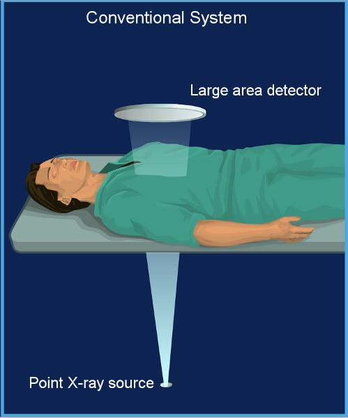
Figure 1. Conventional fluoroscopy system. A conventional system has a single focal spot X-ray source and a large area detector. The patient is positioned close to the detector.
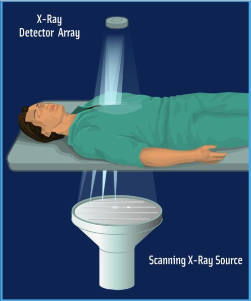
Figure 2. SBDX system. The SBDX system operates in inverse geometry. A large scanning beam X-ray source illuminates a small area detector. The patient is positioned far from the detector.
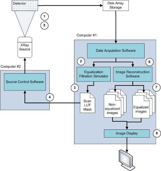
Figure 3. Flow chart of the data acquisition. 1) A non-equalized image of the phantom is acquired. 2) The data is extracted from the disk array. 3) The adaptive exposure algorithm takes this data as input to create an exposure or rescan mask. 4) The rescan mask is combined with the original operating mode in the source control computer. 5) An equalized image of the same phantom is acquired and stored into the disk array. 6) The non-equalized and equalized data sets are extracted from the disk array, and the image reconstruction software reconstructs the different planes of each data set. 7) Both images are the output of the reconstruction software. 8) Both images are displayed.
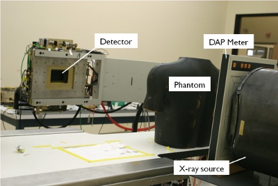
Figure 4. System setup. The phantom is placed on the patient table at isocenter between the X-ray source and the detector. A dose area product meter is placed between X-ray source and phantom.
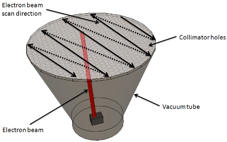
Figure 5. X-ray source. An electron beam is generated by the electron gun and scans each hole of the collimator in a raster fashion. Starting from one side of the collimator, the beam scans each hole sequentially. At the end of the row, the beam is turned off and positioned at the beginning of the next row, and the scan is started for that row. This way the electron beam scans the entire collimator, 71 by 71 holes are scanned eight times in approximately 60ms.
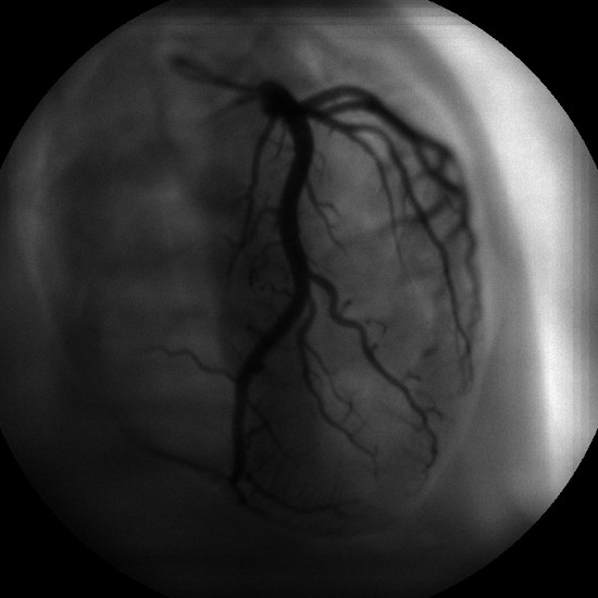
Figure 6. Standard reconstructed image. Reconstructed image of our anthropomorphic phantom displaying the heart with iodinated coronary arteries. The image was taken at 7’’ FOV and 15fps, and a single plane at 45cm from the X-ray target was reconstructed.
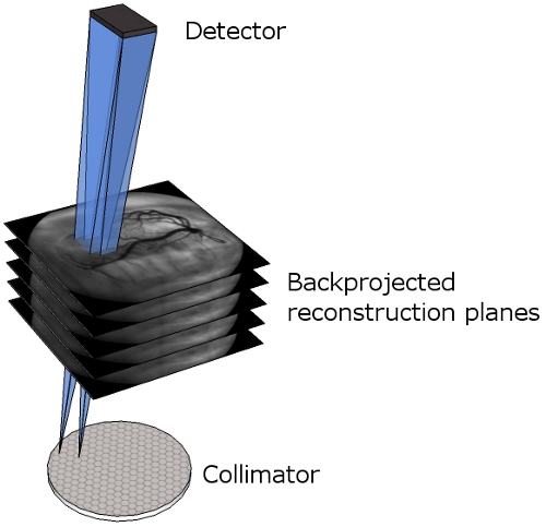
Figure 7. Multi-plane reconstruction. Representation of the different reconstructed planes between the collimator and the detector. The blue cones illustrate how the detector images are backprojected into the reconstruction planes.
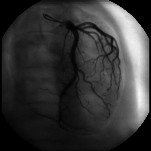
Figure 8. Plane selected image. This image is a composition of 32 planes. In contrast to Figure 6, where only the vessels on the selected plane are in focus, every vessel is in focus.
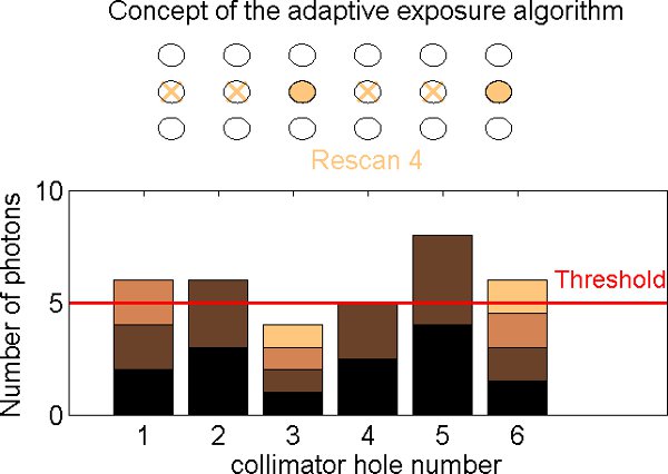
Figure 9. Equalization filtration steps. As the collimator is scanned (top), the detector receives a varying count rate depending on the opacity of the object (bottom). Each collimator hole is scanned up to eight times (eight rescans). On the first rescan, the focal spots are illuminated sequentially along the row, starting from the left, and the flux is measured for each hole. On the next rescan, the illumination is repeated starting at the beginning of the row. For each focal spot, the counts are added to the previous value. If the total number of counts exceeds a previously set threshold, this hole will not be illuminated on the following rescan. In the current implementation this process is performed offline and leads to the creation of a rescan mask that subsequently will be used to acquire an equalized image.

Figure 10. Rescan map generated by the equalization filtration algorithm. Each pixel of this image represents one focal spot of the collimator. The image is therefore 71×71 pixels. The gray level of each pixel represents the number of rescan for that focal spot, from zero (black) to eight (white). We observe that on the right part of the image, the number of rescan is very low. As a result, each of these focal spots will be illuminated only once or twice. This region corresponds to the lung field area of our reconstructed image (Figure 6), where the image is almost saturated because of the low X-ray absorption of this area.
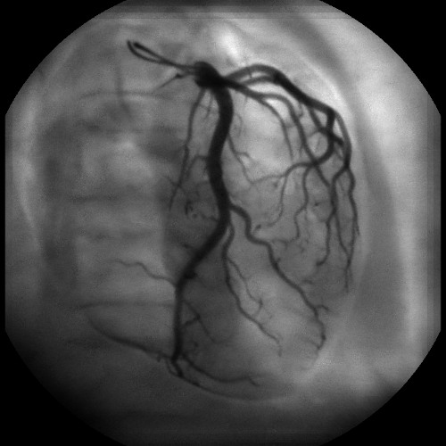
Figure 11. Plane selected equalized image. This image is the output of the reconstruction algorithm after adaptive exposure. This image has been acquired with the same operating mode 7″ 15fps as the standard image (Figure 8), but with adaptive exposure enabled based on the scan mask of Figure 10. The image is more uniform in terms of intensity, and consequently the vessels appear at higher contrast, especially in dark areas. On the right hand side of the image, there is no longer saturation in the lung field.
Movie 1. Animation of the SBDX system. The SBDX system operates in inverse geometry. A large scanning beam X-ray source illuminates a small area detector. The patient is positioned far from the detector. Click here to view the movie.
Movie 2. X-ray generation. At each focal spot, the electron beam hits the tungsten target and X-rays are generated. The collimator focuses the X-ray beam toward the detector. Click here to view the movie.
Movie 3. Image reconstruction animation. This animation represents the process of reconstructing the final image using the detector images. For each focal spot of the collimator (bottom left), the corresponding detector image (upper left) is projected onto the plane to reconstruct (right). In this animation we represent three planes that are being reconstructed at different distances from the X-ray source. Click here to view the movie.
Movie 4. Plane selection. The SBDX system is a tomosynthesis imaging system. The plane to be reconstructed and visualized can be selected by the user. Click here to view the movie.
Movie 5. Multi-plane animation. This video shows the different planes reconstructed at increasing distance from the collimator. Notably, the iodinated coronary arteries go in and out of focus depending on their physical location. Click here to view the movie.
Movie 6. 3D plane selected animation. 3D visualization of the reconstructed focal planes. Focal planes are shifted more with increasing depth. Click here to view the movie.
Discussion
We demonstrate that dose savings are possible using the equalization technique. In this paper we only show how our technique is applied, without discussing implications for image quality. However, it is important to note that our goal is to maintain a target signal to noise ratio in the equalized images. The underlying assumption is that in non-equalized images, the signal to noise ratio is highly non-uniform. In particular, the bright areas like the lung field exhibit higher signal to noise ratios than necessary to perform the diagnostic task. Equalization allows us to lower the signal to noise ratio in these areas and to maintain signal to noise ratios in the darker regions of the image. We are currently performing noise measurement studies to validate our approach. Preliminary results show that dose savings on the order of 30% are achievable at equivalent signal to noise ratio in the dark regions of the image7, 8.
The potential of equalization filtration has been recognized in the scientific literature for many years. However, so far all published implementations involved mechanical shutters or filters, significantly impeding the utility of this approach9,10. Here we demonstrate that equalization can be based on a fully electronic approach, overcoming the problems with mechanical implementations.
In the clinical SBDX system, most of the steps presented here will be implemented in hardware and will be performed in real time during data acquisition. The equalization algorithm will run in real time, and the displayed image will be equalized by default. The algorithm will dynamically adapt its parameters according to the subject being imaged, the motion of the subject, and the changing gantry position. We continue to improve our algorithm, and further development of our method will be necessary in order to facilitate real-time implementation.
Offenlegungen
The authors have nothing to disclose.
Acknowledgements
The authors would like to thank Anne Sandman, Keith Nishihara, and Brian Wilfley from Triple Ring Technologies for their contribution in this project. This work is funded by NIH Challenge Grant 5RC1HL100436-0.
Referenzen
- Martinez, L. C., Vano, E., Gutierrez, F., Rodriguez, C., Gilarranz, R., Manzanas, M. J. Patient doses from fluoroscopically guided cardiac procedures in pediatrics. Phys Med Biol. 52, 4749-4759 (2007).
- Strauss, K. J. Pediatric interventional radiography equipment: safety considerations. Pediatr Radiol. 36, 126-135 (2006).
- Preston, D. L., Cullings, H., Suyama, A., Funamoto, S., Nishi, N., Soda, M. Solid cancer incidence in atomic bomb survivors exposed in utero or as young children. J Natl Cancer Inst. 100, 428-436 (2008).
- Wolff, M., Keevil, J., Speidel, M., Wilfey, M., Wilfley, B., Star-Lack, J. Pilot study with a scanning-beam digital x-ray system. Am J Cardiol. 94, (2004).
- Speidel, M. A., Wilfley, B. P., Star-Lack, J. M., Heanue, J. A., Betts, T. D., VanLysel, M. S. Comparison of entrance exposure and signal-to-noise ratio between an SBDX prototype and a wide-beam cardiac angiographic system. Med Phys. 33, 2728-2743 (2006).
- Speidel, M. A., Wilfley, B. P., Star-Lack, J. M., Heanue, J. A., VanLysel, M. S. Scanning-beam digital x-ray (SBDX) technology for interventional and diagnostic cardiac angiography. Med Phys. 33, 2714-2727 (2006).
- Funk, T., Burion, S., Bechtel, K. L., Solomon, E. G. . X-ray dose reduction by adaptive source equalization and electronic region-of-interest control. , (2011).
- Burion, S., Bechtel, K. L., Lowell, A. P., Heanue, J. A., Solomon, E. G., Funk, T. Real-time equalization filtration: dose savings with region-based exposure control using a scanning-beam X-ray source. , (2010).
- Boone, J. M., Duryea, J., Moore, E. H. Filter wheel equalization in chest radiography: demonstration with a prototype system. Radiology. 196, 845-850 (1995).
- Vlasbloem, H., Kool, L. J. AMBER: a scanning multiple-beam equalization system for chest radiography. Radiology. 169, 29-34 (1988).

