A Real-Time Wearable Electromyography Measurement System for Small Animals
Summary
A protocol is presented for the installation and preparation of intramuscular electrodes, along with an animal-mountable, miniaturized measurement device for electromyography (EMG) analysis in locomotion studies. This system enables the wireless transmission of real-time EMG data for investigating locomotion recovery in stroke model rats.
Abstract
The intramuscular electromyography (EMG) measurement method for experimental animals has been implemented in various ways. Among these methods, tethering cables to external measurement devices can restrict the movement of experimental animals, while implantable devices may cause unwanted side effects due to the constant presence of a device with considerable size and weight. To address these issues, we propose a low-cost, wireless, detachable EMG measurement system and experimental procedure. This article focuses on the surgical installation of intramuscular wire electrodes with small connectors and the development of the wireless system. Notably, in this system, only the wire electrodes are inserted into the animal’s body. Using this system, EMG measurements can be easily performed by attaching the circuit system to a connector installed on the animal’s back, with real-time monitoring achievable on a laptop. The proposed method is explained in a detailed, step-by-step manner, followed by a demonstration involving the insertion of intramuscular electrodes into the hindlimbs of a rat. A treadmill experiment is conducted for a locomotion study, and the resulting electrophysiological signals are subsequently obtained and analyzed.
Introduction
Electromyography involves recording electrical potentials generated by muscle fibers during contraction. These properties are determined by neural activation signals sent from motor neurons to individual muscles. EMG is widely used in rehabilitation, motor, brain, and nerve-related studies, and the measurement methods can be broadly classified into surface EMG (sEMG) and intramuscular EMG (iEMG)1. Surface electrodes offer several advantages, particularly in wearable applications, as they are non-invasive and require a simple preparation process2. In implanted sEMG, the surgical process is simpler compared to iEMG, where the electrode does not need to penetrate the muscle. Despite these advantages, sEMG is prone to signal contamination, such as disturbances at the muscle-electrode interface, motion artifacts, the quality of the electrode contact, and signal crosstalk from adjacent muscles1. These challenges are particularly problematic when the electrodes are placed in close proximity, as is often the case in studies involving small animals. On the other hand, iEMG requires an additional surgical procedure for electrode penetration. Despite the extra procedural steps, this method provides muscle-specific EMG recordings with greater precision and less crosstalk, as the electrodes are permanently embedded in the muscle tissue3. In small animal motor studies, iEMG is preferred since muscle-specific EMG information with reliable electrode installation is critical4.
Several approaches have been reported for acquiring EMG recordings from electrodes in small animals. Tether cables are commonly used to connect electrodes to external measurement equipment5,6,7,8,9,10,11, devices can be implanted inside the body12, or a wireless wearable platform can be placed on the animal13. Tether cables are the most widely reported method due to the availability of compatible commercial equipment for this purpose; however, the tether wires cause discomfort to the animals, and their movement is often constrained by the cables, which may impact the study. Implantable devices offer wireless solutions, but their limited battery life may restrict the duration of experiments. Additionally, the size and weight of permanently installed devices can cause stress and discomfort to the animals, which might affect the study. Wireless power transfer techniques have been proposed to address the issues in implantable devices, but maintaining a reliable energy link to a small device is typically very difficult14. Moreover, exposure to high electromagnetic fields can lead to unforeseen consequences, such as reduced immune function and potential neurodegenerative changes in the brain15,16.
The acquisition system can also be implemented as a wireless, wearable platform that handles signal processing and wirelessly transmits the EMG recordings to a base station. Although this is the preferred method, it presents a technical challenge for the users, and experimental details are often not fully addressed in the literature.
In this work, we present a simple, low-cost, and reliable EMG acquisition method for locomotion studies in small animals. A pair of iEMG electrodes are implanted in the hindlimb muscles of a rat, while the rest of the signal acquisition system, including amplification, an analog-to-digital converter, and wireless telemetry, is mounted on the animal's back. The EMG data is transmitted to a personal computer for real-time monitoring, with data logged locally. A treadmill locomotion experiment is conducted to demonstrate the system in a stroke recovery study.
Protocol
Approval of all ethical and experimental procedures and protocols was granted by the Institutional Animal Care and Use Committee under Application No. CGU1-2021-IA0041. A 7-week-old male Sprague-Dawley rat was used in this study. The details of the reagents and equipment are listed in the Table of Materials.
1. Animal preparation
- Prepare rats at the age of 7 weeks. For safety, house rats of similar weights together, with a maximum of three rats per cage.
- Ensure the rats adapt without stress before surgery. Provide water and food consistently, and replace the bedding periodically.
- During the adaptation period (about 7 days), train the animals to run on a treadmill at a speed of 16-25 m/min for 5 min each day to help them acclimate to the treadmill.
NOTE: If a rat stops or refuses to move as intended, gently tap its buttocks for encouragement.
2. Electrode preparation
- Prepare five stainless steel wires coated with polytetrafluoroethylene, four of them at a length of 140 mm and one at a length of 60 mm.
- Tie three overhand knots on a 140 mm long wire, placing them at 40 mm and 100 mm relative to the knot (Figure 1A).
NOTE: During the insertion of the wire electrode into the muscle, it can be challenging to ensure precise contact and to keep the exposed part of the electrode properly positioned. To address this, a blocking knot is created in the wire to prevent further insertion when pulled, ensuring that the electrode remains stable within the muscle. - For the 140 mm wires, leave a 2 mm gap from the knot on the short side, then partially strip off the insulation using a soldering iron for 2 mm. Fully strip the insulation from the end of the long side by 2 mm. For the 60 mm electrodes, completely remove the insulation at one end by 2 mm and at the other end by 10 mm (Figure 1).
NOTE: The tip of the soldering iron should be thoroughly cleaned to prevent contamination. - Fix the wire by soldering it to the connector accessory after fully removing the insulation (Figure 2B,C).
- Assemble the metal part to which the wire is connected into the plastic housing (Figure 2D,E).
- Attach the connector to a 3D-printed plastic guide (see Table of Materials) that includes holes for securing it to the skin. To prevent the soldered part from contacting the incision site, apply biocompatible cyanoacrylate (Figure 2F).
- Cut a 0.2 mm thick nickel plate and bend it to wrap around the connector, shielding it to prevent potential damage by the animal.
3. Surgery
- Place the rat in an induction chamber (custom fabricated using a transparent synthetic resin) and administer anesthesia using a mixture of 70% nitrous oxide and 30% oxygen, with an isoflurane concentration of 2%-3%. Prepare the necessary surgical instruments (Figure 3).
- Remove the fur using an electric hair clipper to prevent it from entering the incision during surgery (Figure 4A).
- Make an incision of about 10-15 mm using surgical scissors on the skin where the target muscle to be measured is located. Since the fascia lies beneath the skin, and muscles below that, first use scissors to cut the skin, then remove the fascia by gently wiping it away with a clean cloth.
- Make an incision of 5-10 mm around the lumbar region where the connector will be attached.
- Use surgical scissors to create a passage under the skin for the wire to pass from the connector to the target muscle position (Figure 4B).
- Pass disinfected forceps from the muscle position, under the skin, toward the incision site on the lumbar side.
- Prepare the electrode and the connector from the previous stage. Pinch the wire electrodes at the incision site on the lumbar side using the forceps and carefully pull them through to the incision at the target muscle. Once the wire has been pulled out to the location of the target muscle, refer to Figure 4C.
- As shown in Figure 4D, use a suture needle to penetrate the electrode wire into the target muscle.
NOTE: The target muscle for this experiment is the medial gastrocnemius (MG), which is one of the key muscles for analyzing motor tasks17. Since the length of the MG is approximately 18 mm in 7-week-old rats, electrodes should be placed around the muscle's center, with a spacing of about 5 mm, to minimize muscle damage and ensure accurate EMG measurements. It is recommended that the length of the wire penetrating the muscle exceeds 5 mm to ensure that the part with the insulation removed is in good contact with the muscle. - Guide the wire that has passed through and exited the muscle back to its insertion point and secure it with an overhand knot. Cut the remaining wire (Figure 4E).
- After installing the wire electrode in the target muscle, suture the incision site with 4-0 suture thread.
- Suture the incision under the connector. Ensure that the entire wire is inserted into the body and securely sutured (Figure 5A).
- Secure the connector to the animal's dorsal skin using a suture thread, as shown in Figure 5B.
NOTE: Ensure the shield is securely fastened to prevent the animal from chewing on the connector. - Once the surgical operation is complete, discontinue anesthesia and prepare a cage for the animal's recovery.
- Turn on a heat lamp to prevent the animal's body temperature from dropping, and monitor the surgical site for any abnormalities, such as signs of infection, inflammation, or swelling. Disinfect the incision site thoroughly and apply ointment if necessary. Once the rat has recovered from anesthesia, remove the heat lamp.
- Monitor the rat's behavior, including appetite, drinking, and urination.
NOTE: After the surgery, allow the animal to rest for about 2 days before conducting any tests.
4. Printed circuit board (PCB) design and fabrication
- Design the circuit for EMG measurement and digitization to include two analog amplifier integrated circuits (ICs) and a microcontroller unit (MCU). Ensure the amplifier has a bandwidth from 5-740 Hz and a gain of 1300 V/V.
NOTE: Modify the amplifier gain and bandwidth according to the specific requirements of the animal if necessary18. - Include an integrated Bluetooth module in the MCU for wireless communication to transmit the measured data to the host device. A chip antenna operating at 2.4 GHz was used for this experiment.
- Utilize a rechargeable 3.7 V Li-po battery along with a dedicated power management IC for this study.
- Fabricate a PCB for the above ICs on an FR4 substrate. Create the PCB in various forms to meet specific requirements. Refer to Supplementary Figure 1, Supplementary Figure 2, and Supplementary Figure 3.
- Populate the electronic components on the PCB either by soldering or using a heat gun.
5. Software configuration
- Firmware
- Prepare the firmware (Supplementary Coding File 1) to configure a 2-channel ADC with 8-bit resolution and a sampling rate of 2 kSPs. Format the digitally converted data into an array and transmit it via Bluetooth Low Energy (BLE) using the designated software development tool.
- Upload the firmware to the MCU prior to deployment.
- Real-time monitoring program
- Prepare a program to plot the data received via BLE in real-time. For this study, a Python-based plotting application is developed, which also stores the raw data in a specified location (Supplementary Coding File 2).
NOTE: The system can experience a sampling buffer delay of at most 50 ms and a wireless communication delay of approximately 10 ms19,20.
- Prepare a program to plot the data received via BLE in real-time. For this study, a Python-based plotting application is developed, which also stores the raw data in a specified location (Supplementary Coding File 2).
6. Treadmill test
- Connect the battery to the prepared circuit and attach the PCB to the connector, as shown in Figure 6A.
- Execute the monitoring program on the PC and establish wireless connectivity with the circuit PCB.
- Place the rat on the treadmill and monitor the EMG waveform. For this study, the treadmill is set at a speed of 25 m/min (Figure 6B).
7. Data analysis
- Load the EMG data stored in .CSV format.
- Apply signal processing methods to remove unwanted noise and interference signals.
NOTE: Envelope detection and spectral analysis can be further performed to analyze muscle fatigue and symmetry in motor activity.
Representative Results
In this study, a simple wireless method for EMG acquisition is presented. While a surgical procedure is necessary, only the specific area for electrode insertion and connector fixation is partially incised, significantly reducing the burden on the animal. In this demonstration, electrodes were inserted into the lower extremities, but similar electrophysiological studies can be conducted in various other areas using the same method. This approach offers the advantage of continuous electrophysiological signal measurement without the need for tether cables and without imposing behavioral restrictions. The circuit PCB has a diameter of 9 mm, a height of 3 mm, and weighs a total of 3 g. Battery replacement is straightforward, and the proposed system enables continuous monitoring of motor behavior. A photograph showing the attachment of the connector and device, as well as the EMG waveform, is presented in Figure 7.
In this study, a treadmill was used to analyze the rats' movement patterns. The treadmill is an effective tool for analyzing animal movement17, allowing for the assessment of muscular or neurological issues. While it can also be used to study free movement in rats, this experiment specifically aims to analyze movement abnormalities caused by various conditions. To achieve this, continuous and repetitive movement is required, making the treadmill a suitable choice for our purposes.
Various methods can be used to analyze animal locomotion with EMG. Among these methods, the symmetry index was used in the behavioral analysis21,22. The symmetry index measures the balance of activity between two muscles on either side of the body, and we have used it to evaluate recovery from a stroke.
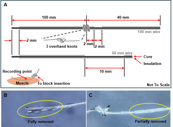
Figure 1: Wire electrode preparation process. (A) Illustration of the wire structure and the position of insulation removal. Three knots should be tied when inserting the wires into the muscles to prevent excessive insertion. (B) The insulation is fully removed at the wire edge. (C) The insulation is partially removed to facilitate muscle contact. Please click here to view a larger version of this figure.
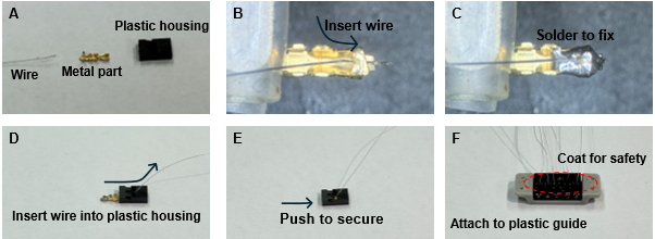
Figure 2: Wire electrode and connector assembly process. (A) Preparation of materials for assembly. (B) Insertion of the wire into the metal component. (C) Soldering the wire to the metal components. (D) Pulling the wire through the opening of the plastic housing. (E) Inserting the wire and metal components into the plastic housing. (F) Completing the assembly for all wires and using cyanoacrylate adhesive to attach the plastic housing to the suture guide (gray part). Please click here to view a larger version of this figure.
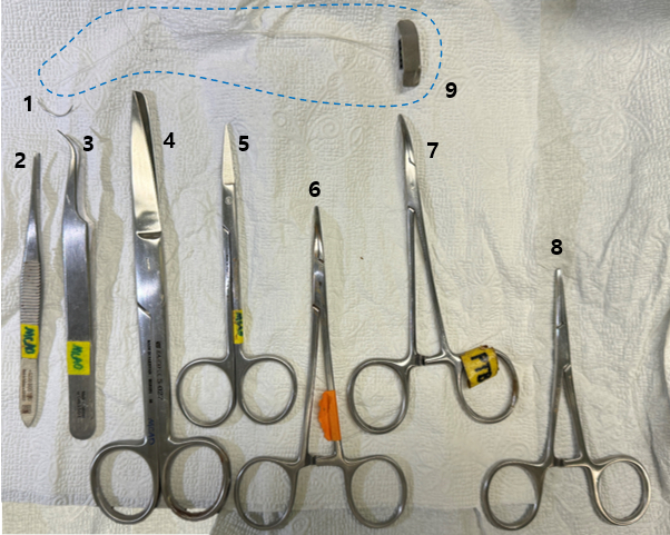
Figure 3: Surgical tools required for the procedure. A collection of surgical tools needed for the procedure, including (1) suture needle, (2) scalpel handle, (3) forceps, (4) surgical scissors, (5) fine scissors, (6-8) needle holder, and (9) prepared electrode. Please click here to view a larger version of this figure.
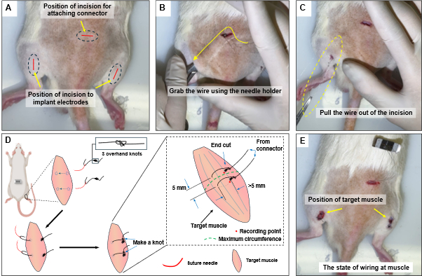
Figure 4: Electrode wire attachment procedure. (A) Incision positions on the back and leg. (B) Inserting the needle holder through the incision to grasp the wire. (C) Pulling the wire out of the incision. (D) Sewing technique at the target muscle, positioning the electrodes around the thickest part of the muscle with a spacing of 5 mm. (E) Final state of the operation being completed. Please click here to view a larger version of this figure.

Figure 5: Connector Placement. (A) Suturing under the connector. (B) Fixing the connector with suture wire. (C) Applying adhesive on top of the connector and placing a metal shield for protection. Please click here to view a larger version of this figure.
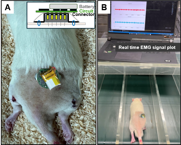
Figure 6: EMG acquisition demonstration. (A) Photograph of the EMG acquisition system mounted on a rat. (B) Conducting a treadmill test at a speed of 25 m/min. Please click here to view a larger version of this figure.
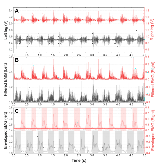
Figure 7: Measured EMG and enveloped EMG waveform. (A) The raw waveform of the measured EMG signal. (B) Filtered EMG signal used to obtain the envelope. (C) Enveloped waveform with a threshold line for symmetry index analysis. Please click here to view a larger version of this figure.
Supplementary Figure 1: Schematic of PCB circuit layout. A schematic representation of the printed circuit board (PCB) circuit layout, illustrating the arrangement of components and connections. Please click here to download this figure.
Supplementary Figure 2: PCB circuit design of the back layer. Design of the back layer of the printed circuit board (PCB), detailing the component placements and routing for the circuitry. Please click here to download this figure.
Supplementary Figure 3: PCB circuit design of the top layer. Design of the top layer of the printed circuit board (PCB), showcasing the layout of components and electrical connections. Please click here to download this figure.
Supplementary Coding File 1: Firmware preparation for ADC configuration. Instructions for preparing the firmware to configure a 2-channel analog-to-digital converter (ADC) with an 8-bit resolution and a sampling rate of 2 samples per second (kSPs). Please click here to download this file.
Supplementary Coding File 2: Python-based plotting application. Description of the Python-based plotting application used in this study for data visualization and analysis. Please click here to download this file.
Discussion
This work presents an electromyography (EMG) acquisition system that is small, easy to implement, low-cost, and wireless. The system effectively prevents signal degradation caused by cables, as it does not rely on any wired external measurement equipment. By mounting the connector on the back instead of the head, the surgical process becomes significantly easier, reducing the risk of complications. This setup also minimizes the chances of the platform bumping into side walls, which can lead to signal artifacts. Additionally, it alleviates neck fatigue, as the concentrated weight is not placed on the head.
The protocol includes several critical steps, notably the precise preparation of the intramuscular electrodes and the careful placement of the connectors. Ensuring that the insulation is stripped accurately and that the knots are tied correctly is essential for preventing excessive insertion during the electrode placement1. Moreover, monitoring the surgical site post-operation is crucial for identifying potential complications early, thereby ensuring the well-being of the animals involved.
While the proposed technique is robust, certain modifications may enhance its effectiveness. For instance, adjusting the length of the electrodes based on the specific muscle size can improve contact quality. Additionally, in case of signal loss or noise during measurements, troubleshooting might involve checking the connections and ensuring that the device is properly shielded from electromagnetic interference6. Providing adequate training to the surgical team can also mitigate procedural errors, improving overall success rates.
Despite its advantages, the device weighs around 3 g, which is not problematic for rats but may cause discomfort in smaller or younger mice. This discomfort could potentially affect their gait patterns, thereby impacting behavioral analysis via EMGore; the device or connector cannot be protected if the rat is left unattended in the cage, which poses a risk of damage13. A metal casing was implemented for protection when the device is not in use, but further developments could enhance this aspect.
The significance of this system lies in its ability to provide continuous, high-quality EMG recordings without the constraints imposed by tethered devices. Traditional methods, including tether cables and large implantable devices, often limit animal movement and may induce stress, thereby skewing results5. The technique offers a more humane approach while maintaining high fidelity in data collection, which is critical for understanding motor function and recovery in various experimental contexts3.
In future work, there are numerous applications for this technique. While the current study focused on the medial gastrocnemius (MG) muscle for assessing muscle symmetry during gait, the methodology can be adapted for other muscles and even extended to electrocardiography (ECG) measurements. Increasing the number of electrodes would enable simultaneous signal collection from multiple sites11, facilitating comprehensive analyses of muscle coordination and function . This advancement could lead to insights into rehabilitation strategies for stroke recovery and other neuromuscular conditions.
In conclusion, the proposed EMG acquisition system presents a significant advancement in the field of animal locomotion studies. By addressing the limitations of existing methods and providing a versatile platform for future research, this system holds promise for enhancing our understanding of motor function and recovery in various experimental settings.
Disclosures
The authors have nothing to disclose.
Acknowledgements
This research was funded by the National Research Foundation of Korea (NRF-2020M3A9E4104385) and Nanomedical Devices Development Project of National Nano Fab Center (Grant number: 1711160154).
Materials
| 0.2 mm thickness nickel plate | Any available vender | ||
| 3D-printing filament | cubicon | A-100 | |
| 7 weeks old RAT | JABIO | SD (DBL) [7W M] | |
| Adhesive | Okong | 1028453 | for securing shield |
| ANT1 | Johanson Technology Inc. | 2450AT07A0100001T | |
| C1, C15, C16, C20 | Vishay | 1n | 0201(0603)metric |
| C10, C13 | Vishay | 100p | 0201(0603)metric |
| C11, C12 | Vishay | 4p | 0201(0603)metric |
| C14, C19 | Vishay | 0.39n | 0201(0603)metric |
| C2, C17 | Vishay | 22n | 0201(0603)metric |
| C3, C5, C6 | Vishay | 0.1u | 0201(0603)metric |
| C4, C18 | Vishay | 2.2u | 0201(0603)metric |
| C7 | Vishay | 4.7u | 0402(1005)metric |
| C8, C21 | Vishay | 1u | 0201(0603)metric |
| C9 | Vishay | 1p | 0201(0603)metric |
| Cage | JEUNG DO B&P | JD-C-02 | |
| Clean cloth | kimberly | 41112 | |
| Connector accessory | Harwin | M20-1060400 | Plastic housing |
| Connector accessory | Harwin | M20-1180042 | Metal part |
| Electric hair clipper | Buzz | RFC-928 | |
| Heat gun | QUICK | 861DW | |
| IC1, IC3 | Analog Device | AD8232 | For EMG measurement AFE |
| IC2 | Nordic semiconductor | nRF52832-CIAA | |
| Isoflurane | Hana Pharm | 657801261 | |
| L1 | Vishay | 3.3n | 0201(0603)metric |
| Li-po battery | TheHan | TW402025 | 13 mm *10 mm * 4 mm, 30mAh |
| Pin header | Harwin | M22-2530505 | |
| R1, R2, R9, R10, R13, R14, R21, R22 | Vishay | 10M | 0201(0603)metric |
| R11, R23 | Vishay | 100k | 0201(0603)metric |
| R12, R24 | Vishay | 1M | 0201(0603)metric |
| R3, R4, R5, R7, R15, R16, R17, R19 | Vishay | 180k | 0201(0603)metric |
| R6, R18 | Vishay | 160k | 0201(0603)metric |
| R8, R20 | Vishay | 768k | 0201(0603)metric |
| Solder wire | Alpha metal | SACX0307 | |
| Soldering iron | Hakko | FX-951 | |
| Stainless steel wires coated with Teflon | A-M Systems | 793200 | |
| Suture needle | AILEE | 301289 | |
| Suture wire | Ethicon | 604G | |
| Treadmill | Daejong Bio | DJ2-243 | |
| U1 | Torex Semiconductor | XC6204B332DR-G | |
| Y1 | Murata Electronics | XRCTD32M000N1P1AR0 |
References
- Farina, D., Enoka, R. M. Evolution of surface electromyography: From muscle electrophysiology towards neural recording and interfacing. J Electromyogr Kinesiol. 71, 102796 (2023).
- Kim, C., et al. A wearable ECG monitoring system using microneedle electrodes for small animals. IEEE Sens J. 23 (18), 21873-21881 (2023).
- Kristl, A. C., Akay, T., Miri, A. Recording forelimb muscle activity in head-fixed mice with chronically implanted EMG electrodes. J Vis Exp. 205, e66584 (2024).
- Manuel, M., Chardon, M., Tysseling, V., Heckman, C. J. Scaling of motor output, from mouse to humans. Physiology. 34 (1), 5-13 (2019).
- Scholle, H. C., et al. A surface EMG multi-electrode technique for characterizing muscle activation patterns in mice during treadmill locomotion. J Neurosci Methods. 146 (2), 174-182 (2005).
- Tysseling, V. M., et al. Design and evaluation of a chronic EMG multichannel detection system for long-term recordings of hindlimb muscles in behaving mice. J Electromyogr Kinesiol. 23 (3), 531-539 (2013).
- Shafer, B., Welle, C., Vasudevan, S. A rat model for assessing the long-term safety and performance of peripheral nerve electrode arrays. J Neurosci Methods. 328, 108437 (2019).
- Teruya, P. Y., et al. Quantifying muscle alterations in a Parkinson’s disease animal model using electromyographic biomarkers. Med Biol Eng Comput. 59 (9), 1735-1749 (2021).
- Kloefkorn, H., et al. Non-invasive three-state sleep-wake staging in mice using electric field sensors. J Neurosci Methods. 344, 108834 (2020).
- Jensen, V. N., Romer, S. H., Turner, S. M., Crone, S. A. Repeated measurement of respiratory muscle activity and ventilation in mouse models of neuromuscular disease. J Vis Exp. (122), e55599 (2017).
- Zealear, D., Li, Y., Huang, S. An implantable system for chronic in vivo electromyography. J Vis Exp. (158), e60345 (2020).
- Shon, A., Brakel, K., Hook, M., Park, H. Fully implantable plantar cutaneous augmentation system for rats using closed-loop electrical nerve stimulation. IEEE Trans Biomed Circuits Syst. 15 (2), 326-338 (2021).
- Ouyang, W., et al. A wireless and battery-less implant for multimodal closed-loop neuromodulation in small animals. Nat Biomed Eng. 7 (10), 1252-1269 (2023).
- Zhou, Y., Liu, C., Huang, Y. Wireless power transfer for implanted medical applications: A review. Energies. 13 (11), 2837 (2020).
- Zymantiene, J., et al. Effect of electromagnetic field exposure on mouse brain morphological and histopathological profiling. J Vet Res. 64 (2), 319-324 (2020).
- Ebrahim, S., Azab, A., Albasha, M., Albishti, N. The biological effects of electromagnetic fields on human and experimental animals. Int Res J Nat Appl Sci. 3, 106-121 (2016).
- Wakeling, J. M., Tijs, C., Konow, N., Biewener, A. A. Modeling muscle function using experimentally determined subject-specific muscle properties. J Biomech. 117, 110242 (2021).
- Westerga, J., Gramsbergen, A. Changes in the electromyogram of two major hindlimb muscles during locomotor development in the rat. Exp Brain Res. 92 (3), 479-488 (1993).
- Tosi, J., Taffoni, F., Santacatterina, M., Sannino, R., Formica, D. Performance evaluation of Bluetooth low energy: A systematic review. Sensors. 17 (12), 28988 (2017).
- . IEEE Health Informatics-PoC medical device communication Part 00101: Guide-Guidelines for the use of RF wireless technology. IEEE Std 11073-00101-2008. , 1-125 (2008).
- Xu, Y., et al. Rehabilitation effects of fatigue-controlled treadmill training after stroke: A rat model study. Front Bioeng Biotechnol. 8, 590013 (2020).
- Nigg, S., Vienneau, J., Maurer, C., Nigg, B. M. Development of a symmetry index using discrete variables. Gait Posture. 38 (1), 115-119 (2013).
Tags

.
